HIGH POWER LIMITER MODULES
RF & Microwave Receivers are used to detect low level signals, therefore require high gain, sensitive circuits at the input to reduce the noise floor. Due to the sensitive nature, these circuits are often susceptible to damage if exposed to high level signals.
In many applications, front end filtering is used to protect the receiver from these unwanted high-power signals; however, even with filtering, it is often the case that high power signals can be present in the receive band and present risk to the receiver front end circuits. This creates the need for a broadband device that will not degrade the sensitivity of the receiver, but protect the receiver in the event of a high level signal. That component exists and is a Limiter, or sometimes called a Limiter Protector.
Typical RF receivers use Low Noise Amplifiers (LNA's) which use highly sensitive transistors with the common device being a HEMT, or P-HEMT to achieve low noise figure. These devices are very sensitive and can easily be damaged if exposed to high power RF. Input powers typically more than 20 mW (+13dBm) can be very difficult to safeguard against in a real-life environment that is exposed to many high-power signals from cell phones and other nearby transmitters.
The use of a broadband diode limiter protector, either stand alone, or in conjunction with an input filter will provide the protection that will enable an LNA to withstand high level signals. Many Mini-Circuits connectorized LNA's are already being developed with integrated internal limiters. The VLM-33+ and the RLM-33+ are connectorized and surface mount alternatives that can be added to an existing system or to an amplifier which does not have an integrated high-power protection. These broadband limiters protect the receiver over an input range for 30 MHz to 3000 MHz, from signals up to 1W. In the presence of high level signals that are within the Limiting Range, the output power is limited to +11.5 dBm (typ) protecting Low noise Amplifiers which have max input handling up to +12 dBm. Furthermore, the typical insertion loss of either limiter is only 0.23 dB making it ideal for use in systems that must maintain low system noise figure but be protected from the occasional high-power signal, and, this model will recover to the insertion loss level (i.e. full sensitivity) typically within 10ns after a high-power pulse is gone.
The Limiter's function of protecting the receiver from high level signals while maintaining very low loss requires the use of a non-linear device. A shunt diode is ideal because it is virtually transparent when biased "off" and highly reflective when biased "on". PIN diodes are commonly used because they can handle high power signals and provide reasonable leakage. In the presence of small signals, the shunt diode does not conduct and therefore represents high impedance, or a low loss condition to the through path. In the presence of high power signals, the RF causes the diode to conduct, driving the impedance to drop well below 50Ω and the entire circuit becomes reflective, preventing the bulk of the energy from getting to following component.
Limiters are specified by a number of Key Parameters:
- Operating Frequency Range - defines the range over which the limiter must protect the succeeding components. Often, this is broader than the operating frequency of the receiver and should span the frequencies where the receiver's components could be damaged; typically where the antenna gain falls off such that high power signals would be attenuated to the point where they would not damage the electronics
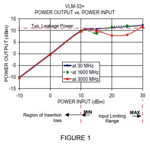
- Insertion loss - defines the small signal throughput loss (S21) of the Limiter. Insertion loss is defined over a dynamic range up to the input limiting range. (See Figure 1)
- Leakage - when high input power is applied to a limiter, only a small portion of the power can pass through the limiter. The small portion is called leakage and is typically specified as an absolute level (dBm or Watts)
- Input Power - defines the limiting range. It is specified at both Min and Max levels. Over this range, the Limiter will follow a specified Δoutput /Δinput characterization. For input signals above the maximum input power, the output will begin to increase again at a greater slope.
NOTE: The Input Power is not to be confused with the Max Rating which is higher and defines the maximum power that the unit can operate without being damaged. - Limiting - The ratio of difference of output power to difference of input power over the limiting input power ranger. (Δoutput /Δinput)
- Recovery Time - The time it takes for the Limiter to recover from a high-power signal. This is a pulsed condition and is defined as the time between the 50% point of the trailing edge of the high-power pulse to the time where the output reaches 90% of the final small signal level.