Performance Change vs. Flexure using Cable Flexure Test Fixture
Introduction
Mini-Circuits FLC Series Test Cables are specifically designed and manufactured for use in stringent test lab environments where cables often undergo bending during normal use. This can result in a change of performance versus flexure. To demonstrate performance change versus flexure, Mini-Circuits has developed a controlled method of test and evaluated our FLC3FT-SMSM+ model by applying various bend radii to a 3ft cable and measuring the change in insertion loss, insertion phase, and VSWR versus flexure normalized to the reference position.
Qualification Testing - Electrical Performance vs. Flexure Test
Cable Flexure Test Fixture
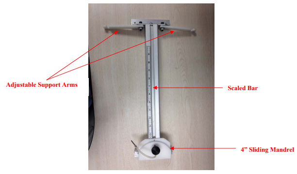
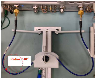
Fixture (B85-L26000-00) used in the setup is designed and built by MCT specifically for the performance vs. flexure test. The fixture as shown in figure 1 below has 2 adjustable arms to support the connector ends when connected to Agilent PNA-X Network Analyzer at Ports 1 & 2. A 3ft flexible cable is wrapped around a 4 inch mandrel which slides along the scaled bar creating the specified bend radius.
Cable Flexure Test Fixture Setup
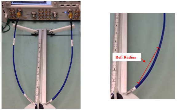
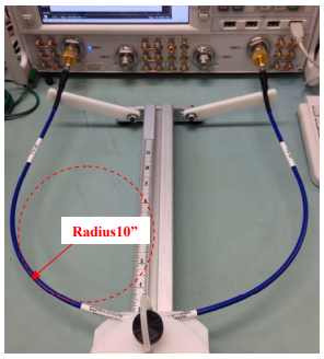
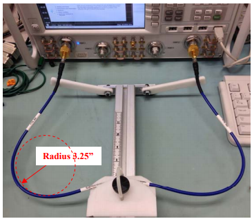
Figures 2 to 5 below show the Flexure Test Setup used in assessing the electrical performance vs. flexure. This flexure test fixture applies a symmetric bend radius to apply a stress on the cable.
Performance Change vs. Flexure Data
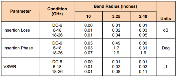
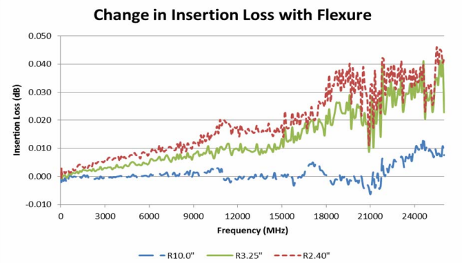
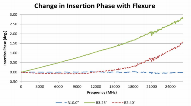
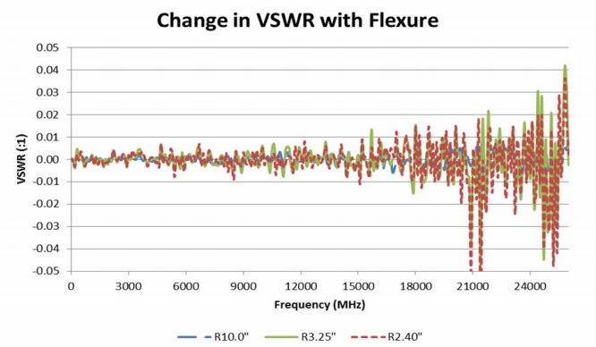
Figure 5 below shows the typical absolute values normalized to the reference position 0, for each electrical performance from DC-26GHz measured using a 3ft cable.
Note: Cable Flexure Test Fixture specifically designed to take measurements using Agilent PNA-X Network Analyzer at Port-1 & Port-2.
Conclusion
Max change in insertion loss at the most extreme case bend radius of 2.40" is 0.05dB, which is found at the frequency range of 18-26 GHz. Max change in insertion phase is 2.9 degrees with a 3.25" bend radius flexure, which is seen at the higher frequencies. Max change in VSWR at the most extreme case bend radius of 2.40" is 0.11 and is also found at higher frequencies. In conclusion, change in performance change versus flexure is minimal and suitable for lab use.