Power Supply Transient Protection for MNA and VNA Amplifiers
Introduction
Shorting of the DC voltage terminal of a MMIC amplifier to ground while DC power is connected can cause permanent damage to the amplifier. This can occur, for example, in a test setup where the amplifier is in a fixture having clip leads for the DC connections; the clips are accidentally moved and they momentarily short the DC and ground terminals together.
Cause of Failure
The short-circuit current is determined by the current-limit setting of the power supply. The abrupt cessation of current, when the short is removed, causes an inductive voltage kick. A few feet of clip lead can have typically a microhenry of inductance, which resonates with the bypass capacitor at the amplifier DC terminal. For a 1000pF capacitor the resonance is in the range of a few MHz. The transient tends to exceed the absolute maximum voltage rating of the amplifier.
Evaluation
The bias circuit in Fig. 1 was used to evaluate the effect of momentarily shorting the DC supply terminal to ground. Amplifier "A" is MNA-4. F1 is a surface-mount ceramic-ferrite EMI filter having 13 and 30dB attenuation at 10 and 20MHz respectively. D1 is a 1N755A zener diode, found effective in preventing damage due to momentary shorting. Testing was done with and without the zener in two circuit configurations: using F1 as shown, and replacing it with a wire jumper.
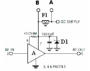
Fig. 2 illustrates the effect of removing a short-to-ground that was applied at the DC input to Model MNA-4. The bias circuit in Fig. 1 was used, including the EMI filter. Voltage was +5V, and the current limit was set to 4A. The oscilloscope was connected at Point B in Fig. 1. A spike occurs at the beginning of the ramp whereby the power supply restores the normal voltage.
Fig. 3 shows the same occurrence, but with greatly expanded time scale. The spike is revealed to have a peak of about 19V, exceeding the 7-volt absolute maximum voltage rating. The device failed as a result of this test.
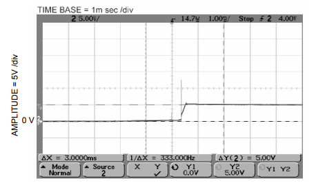
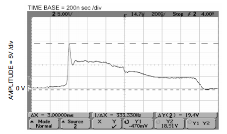
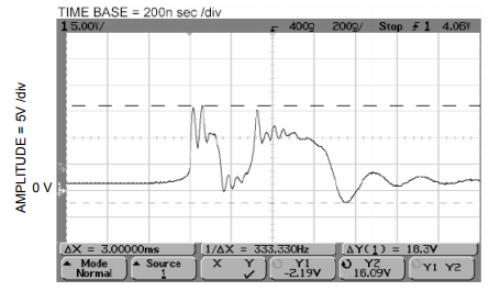
Figure 4 was obtained under the same conditions as for Figure 3, except that a wire jumper replaced the EMI filter. The shape of the transient is different, but the 16V amplitude similarly exceeded the 7-volt rating by a large factor. The device failed as a result of this test.
Prevention
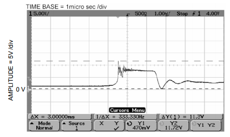
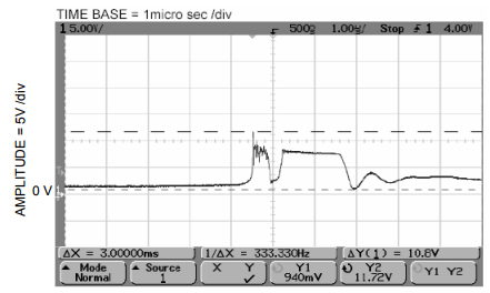
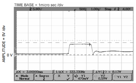
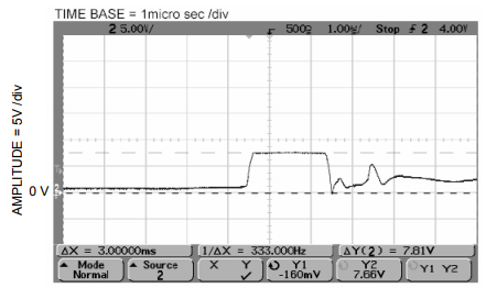
No damage occurred when devices were tested for shorting survival with a 7.5V ±5% zener diode (1N755A) connected between the MNA-4 DC terminal and ground. This value was chosen so that the zener will not conduct when applying voltage up to the absolute maximum rating of the amplifier. Both configurations were tested: with the EMI filter (Figs. 5 and 6) and with a jumper replacing it (Figs. 7 and 8). The DC supply was set at 5V for the traces in Figs. 5 and 7; it was set at 7V for Figs. 6 and 8.
The oscilloscope traces show that the zener diode clamps Point B to a voltage in the range 7.7 to 8.6V. An initial peak of 11.7V occurs when the EMI filter is used, but is absent with the jumper.
The supply was current-limited at 5A. Very similar results were obtained using 1A and 3A current limiting.
Conclusion
A 7.5V zener diode connected from the DC supply terminal of an MNA amplifier to ground can be an effective means of protecting the amplifier from damage due to voltage transients caused by momentarily shorting the DC supply.