Band Pass Filters with Linear Phase Response
Filters with linear phase response are desirable, due to their flat group delay, in many applications, for example in image processing and digital data transmission. Such filters maximally preserve the wave shape of the pasing signal, since they delay all frequency components of the signal by the same amount (i.e. do not cause phase distortion).
Definitions
Phase response Φ(ω) (also "Phase Shift" or "Insertion Phase") of a filter is defined as the phase (or complex angle) of the frequency response.
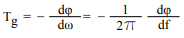
Group delay Tg is the amount of time it takes for a signal having finite time duration, such as a pulse, to pass through the filter. Group delay is defined as the derivative of the phase shift through the filter with respect to frequency:
Linear phase is a property of a filter, where the phase response is a linear function of frequency and, consequently the group delay is constant at all frequencies (flat time delay). This enables the transmission of various frequency components contained in a modulated waveform to be delayed by the same amount while traveling through the filter thus preserving the modulation wave shape and avoiding phase distortion.
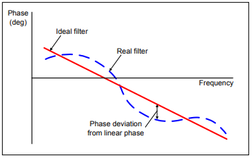
Linear phase response can be presented at filter specification either by mean of "Group Delay Variation" or by mean of "Deviation From Linear Phase". The "Deviation From Linear Phase" is defined as a distance of each point of a real filter Insertion Phase from the ideal filter Insertion Phase (straight line), as presented at Figure 1 below.
The coefficients of the ideal filter (straight line y=ax+b) are calculated according to following formulas ("Least square" method):
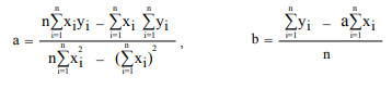
Where x is Frequency point, y is Insertion Phase (normalized to 360°) and n is the number of frequency points.
Retrieving Deviation From Linear Phase of a Filter
Deviation From Linear Phase is received by subtracting the calculated Ideal Insertion Phase from the measured Insertion Phase (S21).
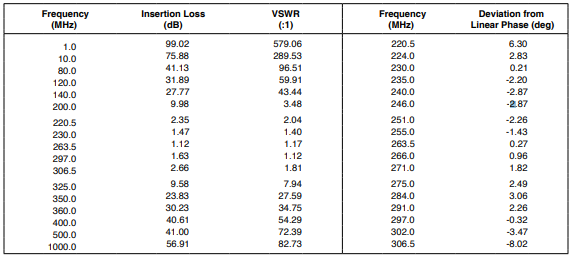
Test results of Mini-Circuits BPF model RBP-263
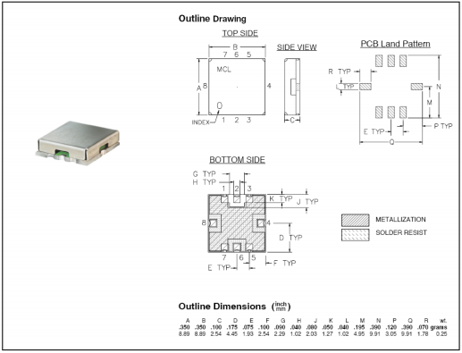
Mini-Circuits offers several Band Pass Filters with linear phase response (currently available RBP-220+, RBP-263+ and RBP-275+). Figures 2 - 4 show the typical data, graphs and outline drawing RBP-263+, for which the deviation from linear phase is defined as ±8 ° typ. at Center Frequency ±43MHz.
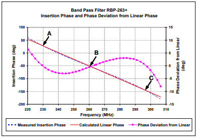
Points A, B, C indicate places where the phase of a real filter equals to the phase of ideal filter (i.e. phase deviation is 0).