Figure of Merit of Mixer Intermod Performance
Introduction
With increased demand on communication systems, today’s receivers and transmitters need to handle multiple carriers, some wanted and some unwanted. When these carriers arrive at the input of a mixer they combine with each other to generate intermodulation products. The most troublesome product to filter out is the third order product. The tolerable level of this product is dictated by the system requirements. Higher IP3, up to a point, can be obtained in a mixer at the expense of LO power in a given design; or, by a better design. Higher LO power means more DC power and more hardware. This paper defines a figure of merit that will be useful in judging the IP3 performance of mixers.
Third Order Intercept Point (IP3)
When two RF signals of equal amplitude arrive at the input of a mixer, intermodulation frequencies are generated due to the non-linearity of the mixing device.
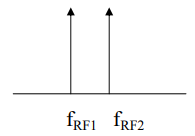
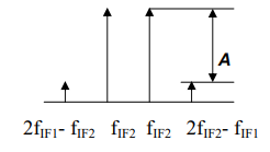
Fig 1a shows a spectrum of two RF signals fRF1 and fRF2 close to each other. Fig 1b shows a simplified spectrum at the IF output. The two third-order products 2fIF1- fIF2 and 2fIF2- fIF1 are predominant intermodulation frequencies, closest to the desired IF output. The spacing between intermod product and the adjacent carrier is the same as between the carrier signals. For example, if the carriers are 1MHz apart, the intermod product is 1MHz from the nearest carrier. Similarly, if the carriers are spaced 1kHz then the intermod product is 1kHz from the nearest carrier. Thus, if the two carriers are close to each other, it becomes very difficult to filter the unwanted intermod product.
Definition of Third Order Intercept point (IP3)
The difference in the power level between the main signal and intermod generated is ‘A’dB (see Fig 1b). Then, the input third order intercept point IP3 is defined as:
(1) Input IP3(dBm)= Pin(dBm) +A/2
In general, in the linear region of a mixer, the intermod product decreases by 3 dB for every dB decrease of RF power. From equation (1), it can be seen that this leads to IP3 being insensitive to RF power level. IP3 is therefore used as a parameter to describe the intermodulation performance of a mixer.
Figure of Merit - IP3 Efficiency of a Mixer
In general, a lower level of intermod product leads to better receiver or transmitter performance. This can be achieved in two ways, by an increase in LO power or by better design. There has been no easy way to quantify how good a design is for intermod performance. Now, a Figure of Merit ‘E’ is being defined as follows:
(2) E= [IP3(dBm)-LO Power(dBm)]/10
It is rule of thumb that IP3 of a well-designed mixer is 10 dB above LO power. Substituting this in equation (2) leads to an E value of '1'. A value of E above one signifies a superior mixer for intermod performance.
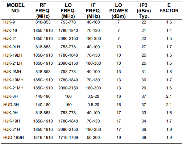
Table I shows a series of FET based mixers developed by Mini-Circuits. The IP3 of these mixers ranges from 21 to 38dBm. At first glance, one would dismiss the 21 dBm IP3 as trivial. On closer examination, the LO power used by this mixer is seen to be only 7dBm. For a 7dBm mixer, 21 dBm IP3 is very good. Still, one has not yet quantified the relative goodness of the mixer. Now, let us look at the E factor of this mixer: it is 1.4, way above the value of '1' used for a normal mixer. This shows that E factor makes it easy to select mixers having high IP3 efficiency.
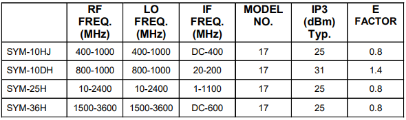
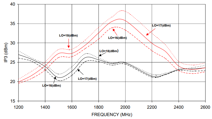
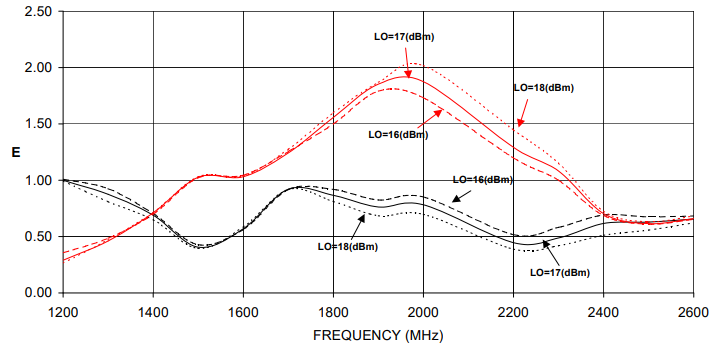
Table I gives a list other FET mixers whose E factor is in the range of 1.4 to 2.1. This is a significant improvement over diode based mixers. Table II lists diode based mixers. Note that the E factor is typically 0.8 except for narrow band mixer SYM-10DH. FET mixers are much more repeatable in production and therefore need no tuning. This reduces the cost of manufacturing. Fig 2 shows the IP3 of FET based (HJK-19H) and diode based (SYM-25H) mixers. Note that the IP3 of HJK-19H is about 7 to10 dB higher than SYM25H in the 1800-2000MHz region. As the bandwidth is increased, diode based mixer and FET mixer have similar IP3. Fig 3 shows the E factor of the same two mixers. Note that the IP3 of the FET mixer is 0.6 to 0.9 higher than the diode mixer in the 1800-2000 MHz range. However, over a wider frequency, the diode mixer provides a higher E factor than does the FET mixer. In addition, the diode mixer has a more constant E factor over a wider bandwidth.
Conclusions:
A new measure for quantifying the IP3 efficiency of a mixer is introduced. This should help selection of the right mixer type and LO-level for a given application. It also helps to highlight mixers with higher IP3 performance.