Low Cost, Triple Balanced, LTCC Mixer
Introduction
Double Balanced Mixers are used widely in frequency translation applications. Some of the advantages of the double balanced mixer are good L-R and L-I isolation and moderate R-I isolation. Triple Balanced Mixers (also called Double Doubly-Balanced Mixers) have three separate baluns for LO, RF and IF ports. This structure helps provide wide bandwidth and good L-R, L-I and R-I isolations, return loss, compression and IP3, all at the expense of 3dB higher LO power. The usual disadvantages of a triple balanced mixer are the number of components that results in large size, and the complexity that makes it an expensive design. Mini-Circuits has overcome these disadvantages by designing a new patented1 LTCC (Low temperature Co-fired Ceramic) based mixer, substantially reducing the size and complexity. It uses a combination of LTCC baluns, a single ferrite-core balun, and integrated Schottky diode quads to realize a small triple balanced mixer.
Operating principle of the Mixer
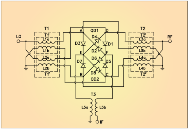
Fig 1 shows the schematic of the mixer. It consists of an LO transformer T1, an RF transformer T2 and an IF transformer T3. Transformer T1 is comprised of transmission line transformers T1' and T1". Similarly, T2 is comprised of T2' and T2". Transformer T3 is also a transmission line transformer. Quads QD1 and QD2 are in monolithic form to obtain superior match.
During the positive half cycle of LO, diodes D1, D3, D6 and D8 are ON. The resulting signal at the IF port is of a particular polarity. During the negative half cycle of LO, diodes D2, D4, D5 and D7 are ON. The resulting polarity of the signal at the IF port is now reversed. This is equivalent to mathematical multiplication, or mixing. The result is sum and difference frequencies of LO and RF signal. Usually the difference frequency is chosen as the IF output signal.
Inter-port isolation is achieved due to the balance of the circuit. Referring to Fig 1, nodes ‘E’ and 'F' are at ground potential for the LO signal. Thus, LO and IF ports are isolated from one another. LO signal from T1 appearing at T2' terminal, and similarly at T2", is of the same polarity and magnitude. Thus, LO and RF ports are isolated.
The RF signal appearing at the IF port is switched every half cycle. By Fourier analysis, it can be shown that RF signal component is not present at IF. The isolation between all three ports is ideal for the usability of the mixer, as it eliminates or reduces the need for external filtering.
Construction of the LTCC mixer
For frequencies below 5 GHz, ferrite based transformers are widely used as baluns. The result is a manufacturing process that is very manually oriented. This becomes a major handicap for large-scale manufacturing. In this new approach, LTCC (Low Temperature Co-fired Ceramic) has been used as the medium to realize two of the baluns making it a compact mixer. Diode quads are used in die form to minimize size and cost. The advantages of the new approach are as follows:
- Small size: 0.25” × 0.3” × 0.2”
- Reduced manufacturing steps
- High repeatability due to integrated components
- Easy to mass-produce
- Low in cost
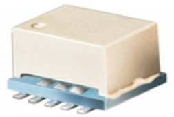
Fig 2 is a photograph of the new mixer
Performance of the mixer
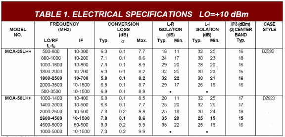
Specifications of two Mini-Circuits triple balanced LTCC mixers are listed in Table 1: MCA-35LH+ and MCA-50LH+.
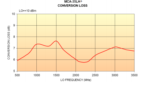
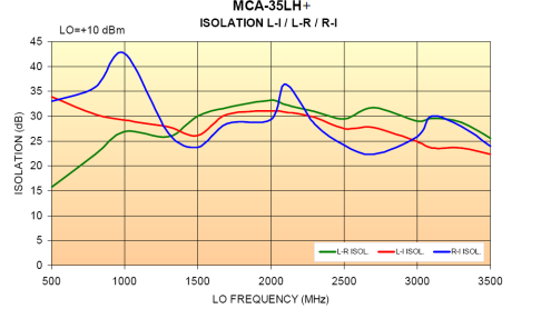
Fig 3 shows the conversion loss of MCA-35LH+. Note that the conversion loss is around 6.5 dB over 1800-2500 MHz. This mixer has typical L-R, L-I and R-I isolation of 30 dB as shown in Fig 4. It also has excellent matching on all three ports, with the following typical return losses:
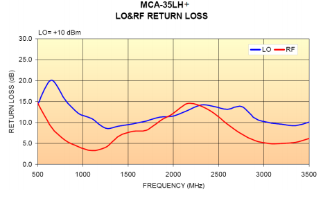
- LO port: 12 dB
- RF Port: 10 dB
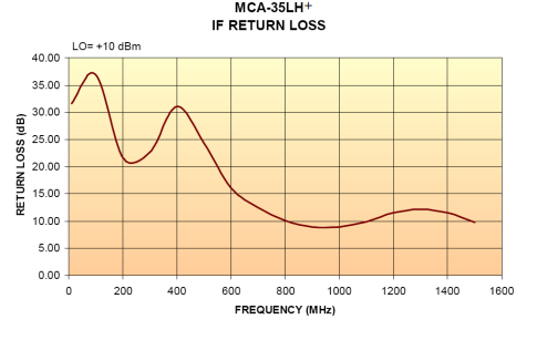
- IF port: 20 dB to 500 MHz and 10 dB to 1000 MHz
Fig 5 shows the return loss of the LO, RF ports and Fig 6 shows the return loss of the IF port.
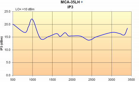
The input third-order intercept point (IP3) of this mixer, in Fig 7, is typically +16 dBm over its entire frequency range. The 1-dB compression point is typically at +6dBm RF input. This mixer has specified performance over 500 to 3500 MHz.
Model MCA-50LH+ is specified for 1000 to 5000 MHz, and has optimized performance over 3000 to 4500 MHz. It has IF bandwidth 10-1500 MHz.
These mixers need 10dBm LO power to perform to specifications.
Conclusion
Mini-Circuits MCA series of Triple Balanced Mixers utilize LTCC. These mixers are small in size, have repeatable performance, and need fewer manufacturing steps. As a result they are lower in cost.. They are ideal for low, medium and high volume markets, as they are easy to reproduce compared to ferrite-core based mixers.