Mixers: Terms Defined, and Measuring Performance
Mixer Terms Defined
Statistical Processing Applied to Mixers
Today's stringent demands for precise electronic systems place a heavy burden on circuit and systems design engineers. To assist them in their work, Mini-Circuits provides the most comprehensive database for its RF/Microwave signal-processing components with computer-automated performance data and specification charts. This capability is achieved by the use of the latest modern automated production and test equipment. Conversion loss specifications, as well as production data, include x-bar (mean) and sigma (standard deviation) values.
Signal naming convention
A mixer is used to provide frequency translation from the input signal to the output signal. When a mixer is used for down-conversion, the input is the RF signal and the output is the IF; for up-conversion the opposite is true. To simplify this application note's presentation, the down-converter notation will be used.
Conversion Loss
Conversion loss is a measure of the efficiency of the mixer in providing frequency translation from the RF input signal to the IF output signal. For given RF and LO frequencies, two nominally equal-amplitude output signals are produced at the sum and the difference of the RF and LO frequencies. Since only one of these products (or sidebands) is utilized in most applications, the specifications given in Mini-Circuits data sheets are for a single-sideband output. If both sidebands are utilized, the conversion loss is 3 dB lower than in the single-sideband case.
Conversion loss of a mixer is equal to the ratio of the RF input power to the IF single-sideband output power, expressed as a positive number in dB. All measurements are based on a 50-ohm system, with local oscillator level as specified for the pertinent mixer type. For example: for a Level 7 mixer it is +7 dBm; for Level 17, +17 dBm; and for Level 23, +23 dBm. When the local oscillator power level deviates from the recommended level, the conversion loss will change slightly.
Conversion Gain
A Mini-Circuits active mixer has an internal amplifier in one or more of the three signal paths. When the amplifier is in the RF or IF path, it generally provides IF output power that is greater than the RF input power. Therefore, conversion gain is specified instead of conversion loss; it is equal to the ratio of the IF single-sideband output power to the RF input power, expressed as a positive number in dB.
Conversion Compression
Conversion compression is a measure of the maximum RF input signal for which the mixer will provide linear operation in terms of constant conversion loss. At low RF signal power, the IF output power and RF input power have a constant ratio, observed as a constant difference in dB. However, when the RF signal power is within about 10 dB of the LO drive level, the IF output power no longer follows the increase in RF input exactly and the ratio between IF and RF power exhibits a change of about 0.1 dB. As the RF power increases further there will be a greater change in the ratio, with conversion loss increasing as the RF input power increases.
The criterion used to describe the deviation from linearity between the RF input power and the IF output is a fixed amount of compression. Mini-Circuits specifies the typical RF input power at the 1-dB compression point, where conversion loss is 1 dB greater than it is at low RF power. Naturally, if an application allows a greater amount of compression, the acceptable RF input power would be higher.
Since the compression point changes with LO drive level, it is important to select a mixer having LO drive level that affords the required compression point for the application. The importance of this performance measure is its utility in comparing dynamic range in terms of maximum input for various mixers.
Conversion compression also provides an indication of the mixer two-tone distortion performance, to be discussed later.
Isolation
Isolation is a measure of the circuit balance within the mixer. When the isolation is high, the amount of "leakage" or "feed through" between the mixer ports will be very small. Typically, mixer isolation falls off with frequency due to the unbalance in the transformer, lead inductance, and capacitive unbalance between diodes. Generally, at the highest frequency of operation, Mini-Circuits double-balanced mixers provide isolation of 30 dB.
The LO-to-RF isolation is the amount the LO drive power is attenuated when it is measured at the RF port, the IF port being terminated with 50 ohms. The LO-to-IF isolation is the amount the LO drive power is attenuated when it is measured at the IF port, the RF port being terminated with 50 ohms. Normally, only the LO isolations are specified, not RF isolation. This is because the RF signal power is much lower than the LO drive level; therefore, RF leakage is usually not a limiting performance factor.
Dynamic Range
Dynamic range is the signal power range over which a mixer provides useful operation. The conversion compression point signifies the upper limit of the dynamic range. The noise figure of the mixer signifies the lower limit of the dynamic range. Since the mixer's noise figure is only about 0.5 dB higher than its conversion loss, the lowest conversion loss is desirable to obtain the largest dynamic range.
DC Polarity
This characteristic applies to mixers having IF response down to DC. DC polarity defines the polarity of the IF output voltage when the mixer is used as a phase detector, with RF and LO signals that are equal in frequency and are in-phase (0°difference). When the data sheet does not specify polarity for the mixer, please consult the factory.
DC Offset
DC offset is a measure of the unbalance of the mixer. For an ideal (perfectly balanced) mixer, the DC offset is zero. DC offset defines the IF output voltage when the mixer is used as a phase detector and a signal is applied only to the LO port, with the RF-port terminated in 50 ohms.
Two-tone third-order intermodulation distortion
Two-tone, third-order intermodulation distortion takes place when two RF signals simultaneously enter the mixer RF port and interact. In practice, this could occur in a multiple-carrier signal environment, or when an undesired signal interferes with a desired one. Of concern is the extent to which the mixer generates intermodulation distortion due to its conversion-loss non-linearity. The products resulting from the interaction may be objectionable when they fall within the IF response.
The third-order spectral components at the IF output are generated as a result of the following third-order frequency terms: |(2 x fR2 - fR1) - fL| and |(2 x fR1 - fR2) - fL|, where fR1 and fR2 represent the two RF input tones and fL represents the LO drive frequency. The minus sign ahead of fL in these expressions applies to down-conversion; for up-conversion replace it with "+".
Intermodulation level is discussed in the next section, headed "Intercept Point".
Intercept Point
A popular method of describing the capability of a mixer to suppress two-tone, third-order intermodulation distortion is the "third-order intercept" approach. The third-order intercept point (IP3) is a theoretical location on the IF output versus RF input curve where the desired output signal (each of the two tones) and the two third-order products (each one) become equal in power, as RF input power is raised. This is illustrated in Fig. 1.
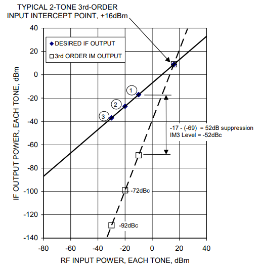
A convenient way to introduce the IP3 concept is to describe how intermodulation products vary relative to desired output signal level. In the example of Fig. 1, -10 dBm RF input produces -17 dBm IF output (Point 1 on the graph), so that conversion loss is 7 dB. The third-order intermodulation (IM3) power is -69 dBm, and the 52-dB difference is called the third-order suppression. We say that the mixer suppresses the third-order products by 52 dB. Another way to express this is to say that the IM3 level is -52 dBc, which means it is 52 dB below the "carrier" (the desired IF output). Whichever way IM3 is expressed, it is important to state along with it the corresponding RF input power, in this case -10 dBm.
Now, if the RF input power were reduced by 10 dB to -20 dBm (Point 2 in Fig. 1), the third-order product level would decrease by a factor of three, or 30 dB. The difference between the desired IF and the IM3 would increase by 20 dB; thus, the mixer would offer 72-dB suppression with two -20 dBm signals at its input. With another 10-dB drop in RF input to -30 dBm (Point 3 in Fig. 1), third-order products would drop another 30 dB and the difference would increase by 20 dB, so that the two -30 dBm input signals would produce third-order products suppressed 92 dB.
When will the desired IF output and the third-order products theoretically become equal? The original input signals were -10 dBm (Point 1 in Fig. 1); the output signals were -17 dBm and the third-order products were 52 dB lower, at -69 dBm. If the input is now raised 26 dB to +16 dBm, the theoretical power of the desired IF output will be 16 dBm -7dB (the conversion loss) = +9 dBm. The third-order products at the output will increase by a factor of three: 3 x 26 = 78 dB, making them (-69 dBm + 78 dB) = +9 dBm. Since the conversion loss is 7 dB, referencing the third-order-product power to the input of the mixer yields 9 + 7 = +16 dBm, thus establishing the Input Third-Order Intercept Point as +16 dBm where the desired signals and the third-order products are equal.
Graphically, the intercept point is obtained by linearly extending both the desired signal curve (past the 1-dB compression point) and the third-order curve until they intersect.
The formula for calculating the intercept point at the output, given the output power of the desired IF signal (POUT, each of the two tones) and the IM3 suppression value ( |IM3 - POUT|, which is the absolute value of the difference in dB between the intermodulation level at the output and the desired IF output), is:
IP3 (dBm) = |IM3 - POUT| (dB) / 2 + POUT (dBm)
To refer IP3 to the input of the mixer, add the conversion loss value in dB.
A rule-of-thumb method for determining the intermodulation level of a mixer is as follows:
- Find the 1-dB compression level (this is the RF input power level that causes the conversion loss to increase by 1 dB).
- Determine the intercept point. For diode mixers, at the low end of the frequency range, this point is about 15 dB above the 1-dB compression point. As the mid- to upper frequency range is approached, the intercept point drops to about 10 dB above the 1-dB compression point. For FET mixers, the intercept point is about 10 dB above the 1-dB compression point.
- Multiply the difference between the intercept point and the per-tone RF input power (equal RF tones) by the sum of the harmonic orders (in this case, 2 + 1 = 3).
- Subtract this number from the intercept point. This yields the intermodulation level in dBm.
For example, given the following conditions for a diode mixer:
- 1-dB compression point at RF input of +1 dBm.
- RF input level -10 dBm, RF at low end of the mixer's frequency range.
- Conversion loss 7 dB.
What is third-order intermodulation power?
Solution:
- Compression point is +1 dBm.
- Intercept point equals 1 dBm + 15 dB = +16 dBm.
- +16 dBm -(-10 dBm) equals +26 dB. 26 dB times 3 (for third-order) = +78 dB.
- Intermodulation power equals +16 dBm - 78 dB = -62 dBm, referred to the input. To refer this to the output, subtract the conversion loss: -62 - 7 = -69 dBm. This is the example illustrated at Point 1in Fig. 1.
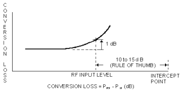
We indicated above that a mixer's intercept point could be estimated from its 1-dB conversion compression point. Fig. 2 illustrates the rule-of-thumb for this. For diode mixers the 15-dB value applies at low frequencies and the 10-dB value at high frequencies. For FET mixers the 10-dB value applies.
Measuring mixer performance
Mini-Circuits policy for product measurement and preparation of specifications is straightforward: present the facts so the design engineer can evaluate product data for his or her circuit and system requirements and arrive at a proper design decision. For mixers, which involve control of 3 signals at different frequencies, particular care is necessary.
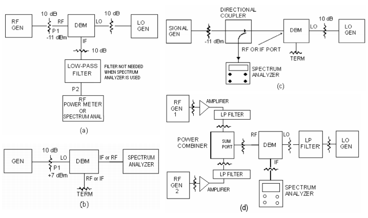
A 50-ohm broadband system is used for all factory measurements on mixers. This uniformity offers the customer a convenient and consistent means to obtain correlation with data generated by Mini-Circuits. Figure 3 presents conceptual block diagrams of test setups for measuring the performance of Level 7 mixers. In actual practice, both for engineering development and for production testing, highly integrated and automated equipment is used to perform the measurements and document the results.
Conversion loss measurements
For conversion loss measurements, Figure 3 (a), fixed attenuator pads are connected to all three ports so the mixer sees 50 ohms at the frequency of interest and all significant harmonics.
For the IF power measurement, a low-pass filter is included before the power meter, to reject all responses other than the desired IF. For example, any LO leakage has no effect on the conversion loss measurement since it does not reach the power meter. If a spectrum analyzer is used instead of the power meter, the filter can be omitted.
Isolation measurements
When measuring LO-RF and LO-IF isolation a pad is placed between the generator and mixer in Figure 3 (b) to ensure a 50-ohm-impedance. Also, a 50-ohm termination is connected to the IF port when measuring the power at the RF port, and vice versa.
When measuring isolation from RF-to-IF, normal LO drive and RF power in the linear operating range are applied. A spectrum analyzer replaces the RF voltmeter. This technique ensures measurement integrity: the power at the fundamental frequency of measurement is distinguishable from other components in the spectrum. For broadband applications, the effects of harmonics can be judged. For narrow-band applications, only the fundamental need be considered.
VSWR measurements
VSWR measurements are made under the same dynamic conditions that the mixer would encounter in practice, see Figure 3 (c). First, let's consider VSWR measurement at the RF port. An LO signal is applied to its port and the unused IF port is terminated in 50 ohms. The RF generator supplies an input level corresponding to linear mixer operation. With the mixer disconnected from the directional coupler, a reference level is obtained (all the RF power is reflected back). The amount of reflected signal depends on the directional coupler used; a 20-dB coupler would establish a reference level 20 dB below the RF input. Next, the mixer is connected to the output of the directional coupler. The spectrum analyzer acts as a narrow-band filter and allows observation at the RF input frequency. The RF power reflected back from the mixer is displayed and can be measured by the calibrated scale on the spectrum analyzer.
The VSWR at the IF port is measured in a similar fashion. In this case, the RF port is terminated in 50 ohms.
VSWR at the LO port is measured with specified LO power applied (+7 dBm, in the example) via the directional coupler, and both the RF and IF ports are terminated in 50 ohms; not shown in Figure 3 (c).
Broadband mixers, it should be noted, exhibit a different VSWR characteristic at different frequencies. Factors causing this include circuit resonances and changes in diode impedances as the LO power level changes. Also of importance is the fact that the input impedances of the various ports are load dependent, even though they are isolated from each other. At high frequencies this effect is more noticeable, because isolation tends to drop as frequency increases.
Two-tone, third-order intermodulation measurements
Two-tone, third-order intermodulation distortion takes place when two incoming signals arrive at the mixer RF port and interact with the conversion-loss non-linearity. See Figure 3 (d). High isolation and low harmonic content in the two RF sources are essential.
For details regarding intermodulation measurement refer to the application note, "Improve Two-tone, Third Order Testing".
