How to select a mixer
Select the proper mixer for your needs. There are hundreds of models available. Under-specify and face marginal performance, over-specify and pay for more than you need. Here's the proper approach.
Mixers are abundant in electronic systems ranging from inexpensive consumer products to sophisticated military hardware. You'll find them in entertainment equipment as well as communications gear, test instruments, radar units and countermeasure systems. Mini-Circuits offers over 400 different off-the-shelf mixer models with thousands of variations available. Different connector configurations, tighter specs, and reliability testing are available on request. Non-optimum mixer selection bears a penalty: under-specify and face marginal performance; over-specify and pay extra for unnecessary performance characteristics.
Making the right choice
Simply stated, there are three basic steps:
- Deciding on a surface-mount, connector, or plug-in version.
- Selecting the mixer "0Level", which is the LO (local oscillator) drive power in dBm required for the application.
- Picking a model that extends over the frequency range involved.
The sequence of these steps follows the manner in which mixer information is accessed when selecting “Frequency Mixers” in the Product Selection menu on the Mini-Circuit website. A general presentation will be given for each of these steps, and then pertinent technical considerations will be discussed in more detail.
At the start it is important to understand your specific needs, so it is strongly recommended that you organize the requirements for your application and put them in writing. Ascertain what frequency ranges (LO, RF, and IF) are involved, and the LO drive you have available. Some applications might specify other factors, such as the acceptable amount of harmonic distortion (caused by mixing of LO and single-tone RF harmonics) and/or two-tone, third-order intermodulation (IM) distortion.
DETERMINE THE TYPE OF PACKAGE AND CONNECTIONS: SURFACE-MOUNT, PLUG-IN, OR WITH COAXIAL CONNECTORS
Generally, the user has evaluated the system requirements and will know beforehand whether the mixer is to be mounted on the user’s PC board or needs to have coaxial connectors. Mini-Circuits has three types of package available: Users typically install surface-mount components via reflow soldering, and many of such products are aqueous-washable. All plug-in (through-hole) mounting units have at least 4 pins to ensure a mechanically rugged connection to the user’s PC board. Some mixers are made with hermetically sealed ceramic diode “quads”. Various off-the-shelf mixers are available with BNC or SMA connectors, and specials can be provided with N or TNC connectors. Many connectored units are available with an optional mounting bracket, as shown on the data sheets. Please describe your connector and bracket requirements when ordering.
DETERMINE THE LO LEVEL REQUIRED
In applications that specify distortion at a particular value of RF input signal power, such a specification might be the governing factor in determining the choice of mixer level; i.e. Level 7, Level l0, Level 17, etc. As a first-order guide for diode mixers, the LO power should be 10 dB greater than the highest input signal level anticipated. Mini-Circuits High-IP3 mixers utilize field-effect transistors, and among most of those mixers it is sufficient to choose one with LO power 3 dB less than the RF power.
In many cases these first-order guidance numbers may be modified. The trade-off is generally between performance and cost. Keep in mind that it is desirable to select the lowest level mixer that will meet the application because it will be more economical to use, and it should result in the least amount of LO leakage within the user’s system.
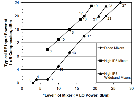
Mini-Circuits offers a wide range of mixers of different levels, from 3 to 27. Referring to Fig. 1, and the discussion on 1 dB compression point on Page 3, select the mixer level for your requirement. For active mixers, which incorporate an amplifier in one of the internal signal paths, as well as for image reject mixers, see the individual data sheets for this information.
DETERMINE THE FREQUENCY RANGE REQUIRED AND SELECT A MODEL
Mini-Circuits offers extremely wideband mixers with a considerable amount of frequency overlap between models. Determine the required frequency range of operation. Then select the mixer whose frequency range specification best "straddles" the range you need. For optimum performance, it is good practice to select a mixer whose midband frequency range (identified by lower-case letter "m" in the specifications) covers the intended operation. Aside from that, all Mini-Circuits mixers perform to specifications with good margin over their entire frequency range. Further, many users operate them outside the specified band with good results, and can still expect to receive high-performing mixers with unit-to-unit repeatability.
1-dB compression point is key to choosing mixer level
What does the 1dB compression point signify? As RF input level is increased, IF output should follow in a linear manner. Eventually, however, IF output increases at a lower rate until the mixer IF output becomes nearly constant.
The RF input power at which the IF output power deviates from linearity by 1 dB is termed the 1-dB compression point. Fig. 1 on Page 2 displays the RF input level at 1-dB compression for each level of mixers of the different types. The 1-dB compression point is useful in comparing dynamic range, maximum output, and two-tone performance of various mixers. It is a basis on which the user can chose mixer level.
The 1-dB compression point, which is one definition for the high end of a mixer’s linear range, is relatively simple to test. It is therefore included on data sheets supplied by Mini-Circuits and by other mixer manufacturers. But, in some applications mixer linearity may be specified otherwise, in accordance with the intended application. For a receiver as an example, two-tone, third-order intermod may be critical. For video applications, percent distortion or intermodulation intercept point may be specified, and in an attenuator measurement system, compression at a given RF input power might be important. A systems engineer needs a convenient means of relating the criterion for a particular application to the published 1-dB compression point. The following linearity criteria will now be discussed in that regard.
- Maximum RF input power anticipated
- Percent distortion
- Intermodulation intercept point
- Two-tone third-order intermodulation, dBc, at a given RF input in dBm per tone
- LO drive power available
- No particular spec to meet
MAXIMUM RF INPUT POWER ANTICIPATED
If you know this number, simply select the lowest level mixer whose RF input level at 1-dB compression exceeds your requirement for RF input power. For example, if the maximum encountered RF level is +5 dBm, select a Level 13 mixer, rated at +9 dBm typical RF input for 1-dB compression.
PERCENT DISTORTION
The percent distortion is usually specified in terms of voltage. Thus, a 0.1% distortion figure means 0.999 of the desired voltage appears at the mixer output. Next, convert this voltage ratio to a power ratio in dB by squaring and taking ten times the log. The resultant figure is the amount of compression for the specified RF input level. Now this must be extrapolated to 1-dB compression for a corresponding RF input level. As a rule of thumb, extrapolation may be achieved by assuming a linear relationship in dB, between compression and RF input level. Thus, a ten-times increase in compression corresponds to ten-times increase in RF input level.
Let's illustrate with the 0.1 percent distortion example, and say it is specified at -10 dBm RF input. The 0.1 percentage corresponds to a relative 0.999 voltage output; squaring this yields 0.998 power ratio or -0.009 dB. We therefore know that 0.1% distortion at -10 dBm input means the maximum allowable compression is 0.009 dB (stated as a positive number). Extrapolating, using the rule-of-thumb relationship, we state that 0.09 dB compression corresponds to an RF of 0 dBm, and 0.9 dB compression corresponds to a maximum allowable RF input level of 10 dBm. So, which mixer is appropriate? A Level 17 mixer, with +14 dBm RF input level at the 1-dB compression point.
INTERMODULATION INTERCEPT POINT
This is a figure of merit relating to the level of intermodulation products generated by a mixer, amplifier, or other mildly nonlinear device. An intercept point can be defined for a second-order, third-order, fifth-order, or other product. For a diode mixer, as a rule-of-thumb, two-tone third-order intercept point (IP3) is approximately 15 dB above the 1-dB compression point. For a FET mixer, the rule-of-thumb is 10 dB. So, if the intercept point value is given, merely subtract the corresponding number of dB from it and pick a mixer having at least that value of 1-dB compression point.
TWO-TONE, THIRD-ORDER INTERMODULATION
For a mixer, two-tone, third-order intermodulation intercept point (IP3) is usually specified with respect to the RF input. Intermodulation (IM) level on the other hand, is measured at the output, either as power in dBm or as dBc relative to the desired IF signal. To find Input IP3 given the output IM power in dBm, first calculate Output IP3 as:
IP3OUT (dBm) = |IM3OUT (dBm) – POUT (dBm)| / 2 + POUT (dBm)
In this formula POUT is the power of the desired IF output signal, IM3OUT is the power of the third-order intermodulation product in dBm, and |IM3OUT – POUT| is the absolute value of the difference in dB between the third-order IM product at the output and the desired IF output.
If output IM is given in dBc, the formula is:
IP3OUT (dBm) = |IM3OUT (dBc)| / 2 + POUT (dBm)
To convert the Output IP3 obtained from these formulas to Input IP3, add the conversion loss value (a positive number, in dB).
Once the output intercept point is calculated, simply subtract 15 dB or 10 dB (see Paragraph 3 above) to find the 1-dB compression point, and select among mixers having that value of 1-dB compression point or higher.
LO DRIVE POWER AVAILABLE
The LO drive is critical since the function of the LO drive is to switch the mixer diodes fully on and off for lowest distortion. So, for optimum performance, select the mixer level to match the LO drive. Mini-Circuits conveniently identifies its mixer levels by the LO drive requirement; thus a Level 7 mixer refers to a LO drive level of +7 dBm. If there are constraints on the LO power available, select the closest mixer level that is lower than the available LO power. For example, if +12 dBm LO drive is available, select a Level 10 mixer.
NO PARTICULAR SPEC TO MEET
Suppose no linearity spec or criterion is given for you application. Choose a Level 7 mixer. Why? Because it is the most popular and offers the widest choice of models at lowest cost.
Frequency range is the final deciding factor
Once the package style and mixer level have been decided you may find a wide variety of models from which to choose. You may notice models with overlapping frequency ranges. Why? So you can choose the optimum mixer for your requirement.
Frequency specs for RF and LO on most of the mixer data sheets are given in three ranges. The lower frequency range, L, covers the lowest specified frequency to one decade (or in some cases, one octave) higher. The upper frequency range, U, starts one octave below the highest frequency. Mid-range, M, covers the frequency range between L and U. For example, a mixer specified from 0.5 to 500 MHz could offer a low-frequency range of 0.5 to 5 MHz, an upper frequency range of 250 to 500 MHz, and a mid-range of 5 MHz to 250 MHz. Try to select a mixer with the highest low-frequency limit for which the mid-range matches your application. Be sure that the IF frequency range covers your requirements, including whether you need it to go down to DC.
What about "Specials"?
When a particular model has been selected the user must determine if the model will meet the electrical performance criteria the user has generated. All MCL mixers are characterized, and a significant number of performance curves and tabulated data describing the models are given on the data sheets and the “View Data” pages on the website. The performance curves on the data sheets describe typical performance. Sometimes the system designer requires higher isolation, lower conversion loss, temperature tracking of conversion loss, unit to unit tracking of conversion loss, selection of higher order harmonic products, less than 100 microvolts of phase-detector DC offset, larger specified bandwidths, etc. Mini-Circuits offers these special performance criteria and many more. Our high volume production enables us to select units to customer specifications at extremely low cost. Mini-Circuits maintains a highly documented system to handle specialized customer requirements.
In summary, contact us about "specials" and we'll do our best to satisfy your needs without excessive cost or delivery date extension. Sometimes, "special" means shipping a quantity of mixers within a very short time span; since Mini-Circuits is the largest manufacturer of mixers in the world, you may be pleasantly surprised by the quick response. Try us.
Practical questions relevant to selecting a mixer
Here are frequently asked questions and their answers.
Q. How critical is LO level in a mixer application?
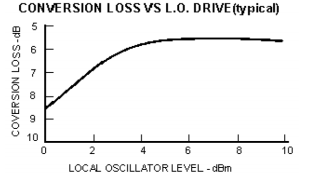
A. The purpose of the LO signal is to switch the mixer diodes on and off. Mixer manufacturers select fixed LO levels so they can test and specify at each particular level. In practice, however, LO drive can vary with minimal effect on mixer performance. For example, a Mini-Circuits SRA-1 unit is specified at +7 dBm LO level; if the LO drive was only 3 dBm perhaps a 0.5 dB increase in conversion loss might take place. Or, a high-level SRA-1H might experience a 0.3-dB increase in conversion loss if LO level was +14 dBm instead of the specified +17 dBm LO. The curve below illustrates how conversion loss varies with LO power for a Level 7 mixer.
Q. I notice Mini-Circuits offers many series of mixers, such as the ADE, MCA1, SIM, SRA, SYM, TFM, ZX05, etc. including over 450 models. Why so many models?
A. Mixers are used in systems covering communications, weapons, test instruments, radar, data transmission and countless other applications. A mixer manufacturer can opt to produce a dozen models and thus, in a sense, force the design engineer to compromise specific system needs by offering a rather narrow selection. Mini-Circuits approach is to offer a wide variety so the designer can buy just what is needed, and thus neither compromise system performance nor pay for more than is really needed That's why Mini-Circuits offers more off-the-shelf models than all other manufacturers combined. But that's not enough. As needs change, new models will become available. For example, the recent demand for higher density packaging has been filled by Mini-Circuits surface-mount mixers such as ADE, MCA1, and SIM series, more than doubling packaging density on a PC board. Finally, although we list over 450 off-the-shelf models, we can supply a great number of variations (such as connector configurations, tighter specs, etc.) at our customers’ request.
Q. What's the difference between "Level 7", "Level 10", and "Level 27" mixers?
A. The different levels of mixers are determined by the LO drive required for a particular application. Thus, each level of mixer has been optimized for a given LO drive, and will offer low distortion even at the maximum input level specified for the mixer. The higher the level of mixer, the lower the distortion expected. It is obvious that the highest level mixer could satisfy most requirements. However, high LO drive would be necessary and the cost of a level 27 mixer is higher than a lower level mixer. Thus, rather than over-specify, select the level of mixer that will optimize your system.
Q. I don't have enough LO drive even for a level 3 mixer. What can I do?
A. Level 3 mixers, although specified for +3dBm LO, will operate well with LO drive as low as 0 dBm. However, there is some degradation: about 0.5 to 1.5 dB additional conversion loss among various Level 3 models. Also, the upper frequency limit might be slightly reduced and there may be increase in two-tone, third-order IM.
Q. I am operating over a wide bandwidth and my LO drive level changes by about 3 dB. How should I take this into account when I select a mixer?
A. The preferred approach would be to determine your lowest LO drive level over the band and then select a mixer for this drive level. Remember that as LO level increases over the nominal (to +10 dBm for a level 7 mixer), conversion loss remains flat and thus optimum performance will be maintained and not degraded.
Q. From my requirement for intercept point, I have selected a Level 13 mixer. Can I apply a +7dBm LO drive and expect the high performance specified in the data sheets?
A. No. Performance to the specifications take place when the mixer diodes are driven fully "on" by the LO drive. Therefore, when LO drive is insufficient, the diodes operate on a lower-current portion of their I-V characteristic curve. The resulting increase in diode non-linearity increases distortion of the output signal. That is why Mini-Circuits offers so many different mixer levels, so that the user can choose optimally.
Q. I need a mixer with flat conversion loss over my frequency range spec. How do I go about selecting a model?
A. Conversion loss over the midrange response of a mixer is usually flat. So select a mixer that has a midrange response covering the frequency range you need. Also, the VSWR of the mixer (especially the RF and IF ports) should be checked in order to minimize mismatch errors which could compromise the conversion loss flatness.
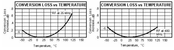
Q. I expect wide temperature extremes for my latest RF design project and mixer conversion loss vs. temperature concerns me. What advice can you offer?
A. For extremely cold environments (down to -55°C), to maintain flat conversion loss, pick a mixer that operates a minimum of two octaves below your lowest frequency of operation. For example, if your application involves operation at 30 MHz, select a mixer that extends to 7.5 MHz or lower. Why? The permeability of the ferrite core in the mixer transformer will drop at reduced temperature, resulting in higher losses or frequency fall-off at the low end of the band. In extremely high-temperature environments, the mixer diodes will be the predominant factor affecting conversion loss. Diode impedance will change and cause mixer mismatch to upset flat conversion loss. So, select a mixer whose upper frequency is an octave higher than that of your application. For example, if you are concerned with high-temperature performance at 500 MHz, select a mixer good up to 1000 MHz (such as the SRA-2CM or TFM-2).
Q. Do you supply a mixer with a specified maximum VSWR?
A. Generally, a maximum VSWR spec is not given in the mixer data sheets. You can find typical performance data of mixers including VSWR on our website. As a general rule, try to select a mixer whose midrange covers your frequency band of interest. If you need to specify a maximum VSWR requirement, Mini-Circuits can screen and test to meet your needs.
Q. My application involves maximum RF input signal levels of -20 dBm. I notice the 1- dB compression point specification of many mixers is at +1 dBm and higher. Should this spec be of concern to me?
A. Yes, if two-tone, third-order IM is critical or if receiver response to unwanted signals is important. The 1-dB compression point is related to the intercept point, which is a "figure-of-merit" of the linearity or distortion characteristic of a mixer. It also indicates the susceptibility of the mixer to unwanted signals.
Q. I need a mixer that nominally operates at + 10 dBm LO drive but requires protection against sudden surges of RF input power as high as 200 mW. What mixer should I select?
A. To avoid damage from a 200 mW input signal, choose a Level 17 mixer. Reason: a Level 17 mixer contains eight diodes, and is rated at 200 mW maximum RF power. But, there is a penalty. For minimum distortion, you'll require +17 dBm LO drive, which may be higher than your original intent. Or, you can operate at a lower LO drive and accept an additional conversion loss of 1.0 to 1.5 dB.
Q. l have an application requiring an RF frequency response from 100 Hz to 10 MHz. I don't see any mixers specified with an RF this low. What can I do?
A. One of the characteristics of double-balanced mixers (DBM) is that for most models IF response extends down to DC. All ports of the DBM are balanced and isolated from each other. Therefore, if the high-frequency response of the IF port is sufficient to handle the RF signal in your application, simply connect the RF input signal to the IF port and take the IF output from the RF port. Make sure the RF frequency response of the mixer will accommodate the IF frequency requirements, since in this configuration the IF (formerly the RF) does not go down to DC.
Disadvantages? Yes. Generally, the linearity characteristic will not be as good as with the signal connected in the conventional manner. Also, there is a danger that transients at the RF port (previously the IF port) can damage the diodes internal to the mixer.
