DIY Low-Cost Power Splitters
Ever expanding applications of RF and Microwaves for Wireless and Cable applications have revived the development efforts of components at these frequencies. There is a continuing demand to reduce the cost and increase the performance and quality at the same time. Mini-Circuits is working to satisfy these goals and has introduced a new splitter series to satisfy the demands of the market. These splitters are designed to need only commercially available low-cost off-the-shelf chip resistors and capacitors as external components, and are designed for automated manufacturing to achieve low overall cost.
What Constitutes a Power Splitter:
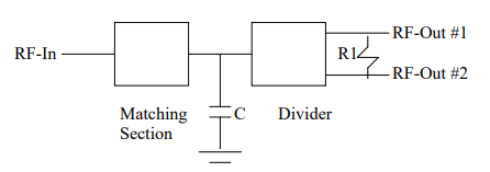
Fig 1 is the block schematic of a two-way power splitter. It consists of a divider section, a matching section, a resistor R1 and capacitor C. The function of the divider section is, as the name implies, to divide the input signal into two parts. The matching section together with capacitor C performs wide-band matching at all ports. Resistor R1 helps provide wide-band isolation between the two RF output ports. The matching and divider sections form the heart of the splitter. They are realized using magnetic cores. The matching and divider sections are integrated into a single unit, and are herein afterwards called the splitter. The next section describes the splitter.
Construction of the "TCP" device
TCP-series splitters use one ferromagnetic core transmission line transformer for power division and another similar transformer for matching. The base of the device is made of plastic with embedded leads, which makes the construction very rugged. The leads are solder plated for excellent solderability. All connections from the transformers to the header are made by welding. This helps to ensure preciseness of the assembly, with resulting high performance repeatability, as well as preventing any disconnection during reflow.
Performance of the Splitter
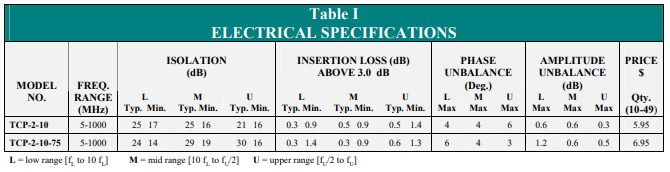
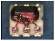
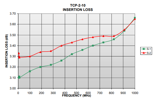
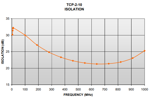
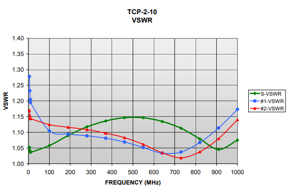
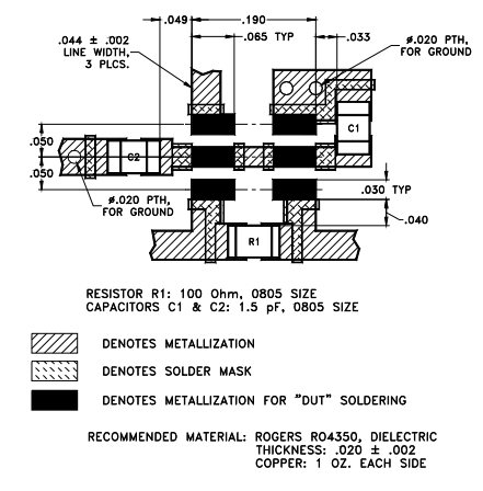
Mini-Circuits has introduced two splitters, each covering the frequency range of 5 to 1000 MHz. TCP-2-10 is designed for 50 ohm and TCP-2-10-75 is for 75 ohm characteristic impedance. Fig 2 is a photograph of the splitter and Table I gives the specifications. Fig 3 shows the insertion loss of TCP-2-10. The insertion loss of the splitter is typically 0.5 dB above the 3 dB split over the band. Fig 4 shows the isolation vs. frequency, which is typically 25dB over the band. Fig 5 shows VSWR vs. frequency at all three ports, which is typically 1.1:1. Circuit board layout plays an important in the performance of the splitter. In order to minimize parasitic effects, the suggested layout shown in Fig 6 should be used. The external components, resistor and capacitor should be of 0805 size. The chip resistor should have a nominal value of 100 and 150 ohms for TCP-2-10 and TCP-2-10-75 respectively. Each capacitor should be of NPO type with a nominal value of 1.5pF. For TCP-2-10 use both C1 and C2 as shown in Fig 6; for TCP-2-10-75, use only C2.
Conclusion
Two power splitters have been introduced to operate over 5-1000 MHz. Due to all-welded connections the splitters are very rugged. The product has been designed to be manufactured in automated set-ups which helps lower the cost. Further cost reduction is obtained by designing the unit to work with a low-cost off the shelf chip resistor and capacitor used as external components.