Miniature Power Splitter
Introduction
Power Splitters below 1 GHz are traditionally made using ferrite transformers. These splitters provide multi-decade bandwidth and are compact. Splitters presently available on the market are 0.25 x 0.31" in size. Further reduction in size has been possible using external resistors and capacitors. Mini-Circuits now has developed a wide band miniature splitter in a small package, 0.15x 0.15 x 0.15", which does not need any external components. This reduced size is made possible by a technique that integrates all the elements into the package. The resulting splitters should enable customers to conserve PCB space on the mother board and allow them to build multiple output-port splitters such as 4-way, 8-way by cascading the splitters. These splitters are available in tape and reel for high speed automated pick and place manufacturing.
What Constitutes a Power Splitter
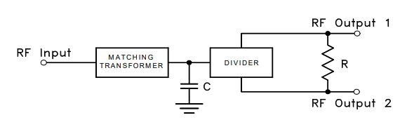
Figure 1 shows a block diagram of a power splitter. It consists of an input matching section, a divider section, a capacitor and a resistor. In a 50-ohm system, the impedance at the input of the divider is close to 25 ohms. The matching transformer converts this to 50 ohms at the RF input to provide a good match. Normally a capacitor C is required to match the reactive part of the impedance. The resistor R plays a critical role in providing isolation between the two RF output ports.
Construction
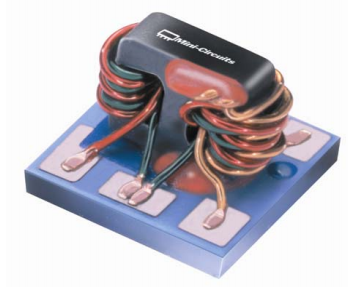
As seen in Figure 1, the unit consists of four components. Traditional construction of the splitter requires a large PCB area (of the order of 0.25 x 0.31"). In the new design, the base of the unit is constructed using Blue Cell TechnologyTM. This technology enables embedding the resistor and capacitor in its body. A ferrite transformer is used to perform the power splitting and matching function. All connections are accomplished by the Mini-Circuits proprietary welding process. Connections are brought to the bottom of the board by reliable via connections. The resulting unit is very compact and measures 0.15x0.15x0.15". Figure 2 is a photograph of the splitter.
Electrical Performance & Repeatability
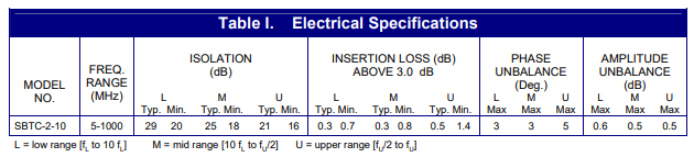
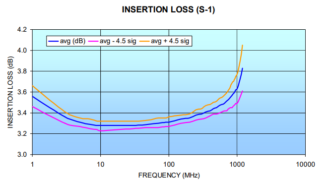
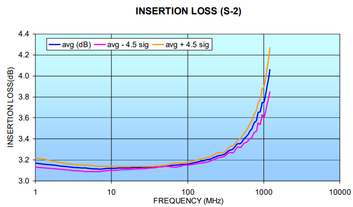
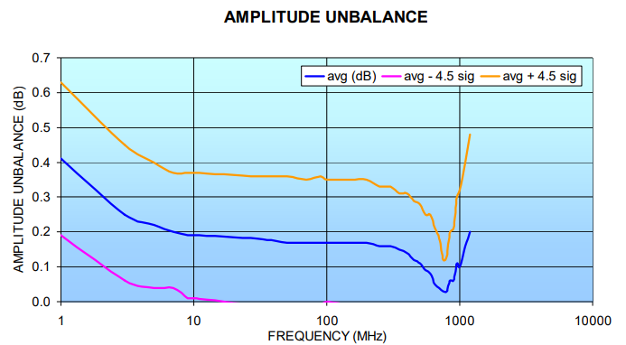
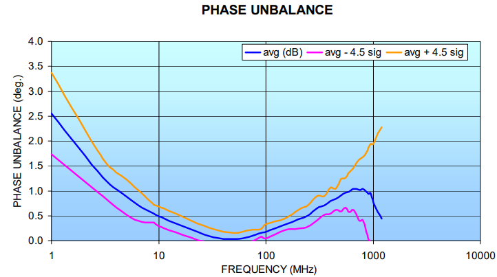
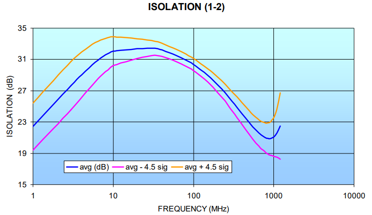
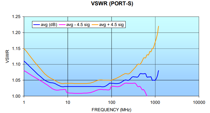
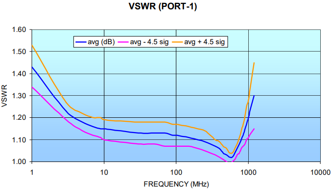
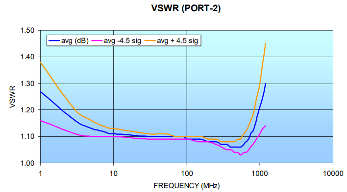
Repeatability of components is a prime concern for system designers. The compact nature of the design results in very repeatable performance. Figures 3 and 4 show the S-1 and S-2 insertion loss of the splitter. Each graph has three curves. The first curve shows the mean, the second mean plus 4.5 sigma, and the third mean minus 4.5 sigma. As can be seen, the design results in a very small standard deviation (0.02 dB, typical) so that the variation is trivial from unit-to-unit. Figure 5 shows the amplitude unbalance, which is the difference of output power between ports 1 and 2. Unbalance is typically 0.1 dB with a standard deviation of 0.04 dB. Figure 6 shows the phase unbalance of the splitter. Again, the variation is very small (standard deviation is 0.10 typically). Figure 7 shows the isolation between the two RF output ports. It is typically 20 dB to 1000 MHz. This parameter is normally very sensitive to assembly parasitics in other designs and varies from unit to unit. In this design, the standard deviation for isolation is typically 0.5 dB, which signifies very low variation. Figures 8 to 10 show the VSWR of the unit. Match is excellent, and VSWR is typically 1.15:1. This unit is specified to operate over 5-1000MHz and is usable over 1 to 1200 MHz. The unit can handle 0.5W as a splitter and 0.125 W as a combiner. Table I lists the specifications of the splitter.
Conclusions
A low cost, miniature, high performance splitter has been developed to cover the frequency range of 5-1000 MHz. This splitter, besides being small, has performance equal to or better than similar splitters built in bigger size.