Diminutive Impedance-Matching Splitters
These tiny power splitters deliver full-sized performance transforming between 50Ω and 75Ω, from 5 to 1000 MHz.
Traditionally, power dividers/combiners are invaluable passive components that allow transmitters and receivers to combine or divide signals as necessary. Component availability for characteristic impedance of 50Ω is ample. A mixed impedance splitter (50Ω at input and 75Ω at output, or 75Ω at input and 50Ω at output) can help in certain signal processing applications, such as realization of 75Ω balanced amplifiers.
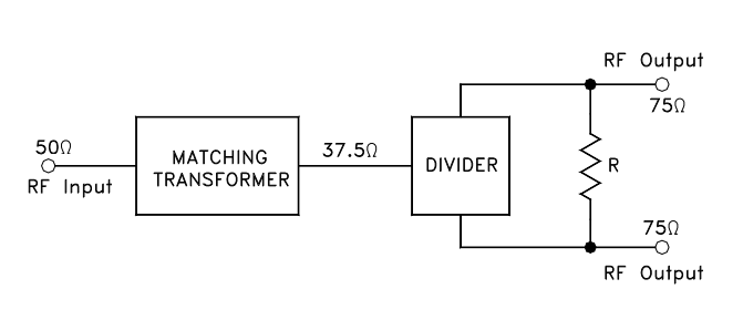
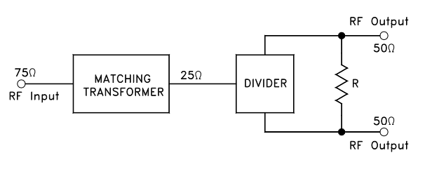
Basically, a power splitter is formed of an input impedance-matching section, a divider section, and a resistor. Consider a system that needs to split a signal from input at 50Ω to two outputs at 75Ω. As shown in Fig. 1, the impedance at the input of the divider is nominally 37.5Ω. The matching transformer converts this impedance to 50Ω input with minimal signal power loss. Oppositely, a system to split a signal from input at 75Ω to output at 50Ω is shown in Fig. 2. The impedance at the input of the divider is close to 25Ω. The matching transformer converts this low impedance to 75Ω at the RF input.
Construction
The base of Mini-Circuits matching splitter models SBTC-2-10-5075 and SBTC-2-10- 7550 is constructed using Blue CellTM technology, which utilizes low temperature cofired ceramic (LTCC). This makes it possible to embed the resistor and part of the matching network within the power-splitter circuitry, while the base supports a ferrite transformer to form the divider and to complete the matching function. Connections between components are formed through the company's proprietary welding process. Please refer to application note AN-40-004 for reflow soldering guidance.
Performance
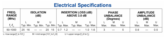
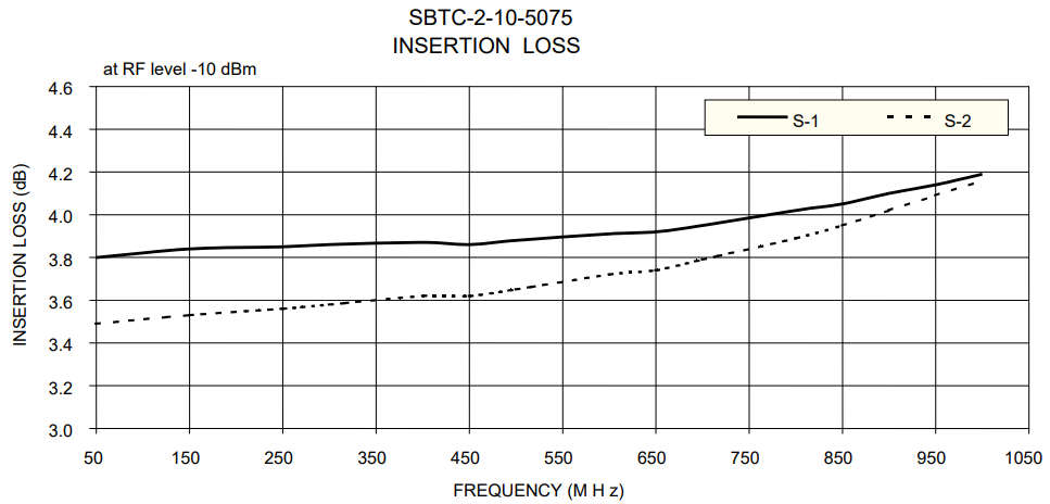
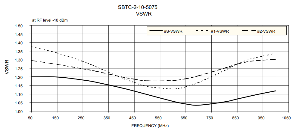
Model SBTC-2-10-5075 is a two-way splitter from 50Ω input to 75Ω output. It shows about 1dB insertion loss up to 860 MHz and 1.2dB at 1000 MHz (above the 3dB split); see Fig. 3. Also, it has excellent VSWR (Voltage Standing Wave Ratio) as shown in Fig. 4: 1.05 - 1.20 (typ.) at the input (Port S) and 1.15 - 1.35 (typ.) at the outputs (Ports 1 and 2) from 50 to 1000 MHz. The specifications are given in Table 1.
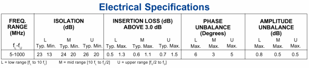
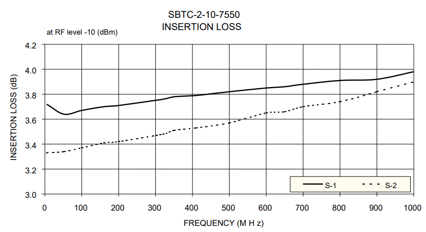
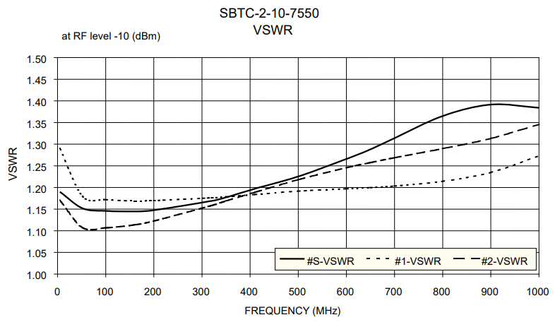
Model SBTC-2-10-7550 is a two-way splitter from 75Ω input to 50Ω output. It has less than 1dB insertion loss from 5 to 1000 MHz as Fig. 5 shows. VSWR is 1.25.(typ.) up to 600MHz at both input and output. It rises at higher frequencies; peaking at 1.40 (typ.) at the input. See Fig. 6. The specifications are in Table 2.
Both of these devices can handle input power level up to 0.5W when used as a splitter, and 0.125W when used as a power combiner.
What are the applications for these products?
Example 1:
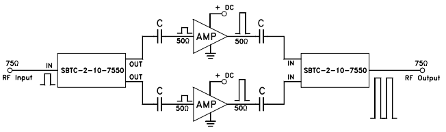
Usually, a cable system operates at 75Ω impedance. But, most of RF amplifiers have 50Ω impedance. By using the circuit shown below, Fig. 7, amplification of RF signals in a 75Ω system is possible with 50Ω amplifiers. With impedances matched in the circuit, maximum power will be transferred and the system designer has more choice of amplifiers.
Example 2:
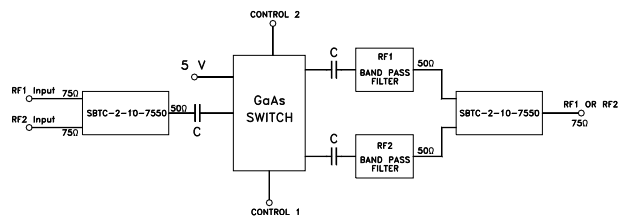
Many RF communication systems are using cable network now, and therefore require wide-band 75Ω RF switches. RF communication systems have traditionally been implemented in 50Ω impedance; to match, switches are generally designed for 50Ω. A pair of power splitters with 50Ω input and 75Ω output will enable a 50Ω switch to be used in a 75Ω cable network. Fig. 8 shows a circuit for selection of cable signals that can be used for network connection.
Conclusion
These newly developed products have diminutive size, small power loss and wide bandwidth. They combine two functions in one device - power splitting/combining and impedance matching, and have many practical applications.
