Surface Mount LTCC Quadrature Splitters
Introduction
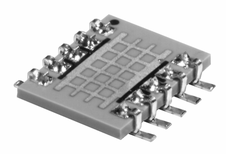
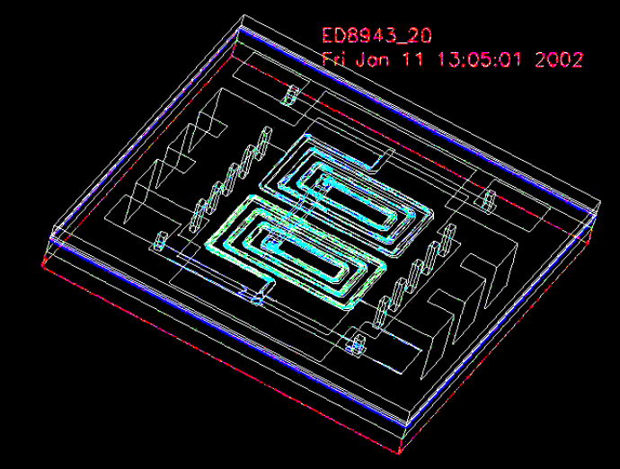
Transmission line 90° splitters (also called quadrature splitters) are quarter-wave in length. Thus, the overall length is dictated by the frequency of operation. Folding the line like a meander or like a spiral can reduce the mechanical length. Interaction of transmission lines in various layers and between the folded lines can cause problems unless design is done well, and it is not simple. Full electromagnetic analysis has to be performed to optimize the performance to account for the interaction effects. Such splitters can now be realized using LTCC (Low Temperature Co-fired Ceramic) technology. LTCC technology uses thin layers of ceramic on which conductors are printed using noble metals. Various layers are bonded to each other by firing around 850° C. This technique provides two important properties. First, insertion loss is lower than that can be realized in a conventional high temperature ceramic technology, as the noble metals provide lower loss. Second, it provides a hermetic seal. Hence, these splitters are ideal for demanding environments and applications such as military. But, they are equally usable in commercial environments due to their low cost. Use of ceramic as material helps heat dissipation and performance variation over temperature. For the QBA-07, the package consists of ten leads attached to the substrate, forming a robust and reliable assembly. These leads are solder plated for excellent solderability. Figure 1 is a photograph of the splitter and fig 2 shows an X-ray view.
Performance
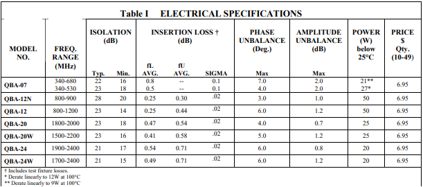
Requiring 0.25 by 0.3 inch of PC board mounting area, the low profile (0.050 in) QBA-07 splitter operates from 340 to 680 MHz. The average insertion loss is typically 0.8 dB across the full band, amplitude balance is 0.7dB, with phase unbalance of 3 degrees. Isolation is 22 dB across the band. As mentioned before, one of the major advantages of LTCC is the stability of performance over temperature range. Variation is typically of the order of 0.1dB for insertion loss, 1 dB for isolation, and 0.5 0 for phase unbalance over -400°C to 850°C. Recommended footprint is provided in the data sheet of the splitter and can be down loaded from the splitters respective model dashboard. Table I shows the specifications of the other splitters available in this family.
These splitters can operate up to 25 watts of input power, enabling their use in moderate to high power circuits. The solder melting temperature determines power handling of these splitters. The unit itself can withstand much higher power. Power capability tests were conducted on a similar splitter in the series, QBA-12N, and indicate that the unit is capable of handling greater power than rated (50W) at room temperature. With 120W of RF input power, the leads became detached from the motherboard due to the melting of the solder connection. The unit was reattached, and it performed as before with no noticeable change in performance. Continuous operation of this splitter at 50W for a week indicated no performance degradation.
Conclusion
LTCC quadrature splitters present a major technological advance by offering improvements in performance, size, power handling capability, and temperature stability. In addition, availability is off the shelf and they are price competitive for both military and commercial environments.