Understanding Power Splitters
How they work, what parameters are critical, and how to select the best value for your application.
Basically, a 0° splitter is a passive device which accepts an input signal and delivers multiple output signals with specific phase and amplitude characteristics. The output signals theoretically possess the following characteristics:
- equal amplitude
- 0° phase relationship between any two output signals
- high isolation between each output signal
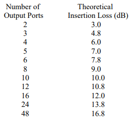
- insertion loss as follows:
Since the 0° power splitter is a reciprocal passive device it may be used as a power combiner simply by applying each signal singularly into each of the splitter output ports. The vector sum of the signals will appear as a single output at the splitter input port.
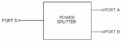
The power combiner will exhibit an insertion loss that varies depending upon the phase and amplitude relationship of the signals being combined. For example, in a 2 way 0° power splitter/combiner, Fig. 1 if the two input signals are equal in amplitude and are in-phase then the insertion loss is zero. However, if the signals are 180° out-of-phase the insertion loss is infinite. And, if the two signals are at different frequencies, the insertion loss will equal the theoretical insertion loss shown above.
The power combiner will also exhibit isolation between the input ports. The amount of isolation will depend upon the impedance termination at the combiner output or sum port. For example, in the 2 way 0° power splitter/combiner of Fig. 1 if port S is open then the isolation between ports A and B would be 6dB. And, if port S is terminated by a matched impedance (for maximum power transfer) then the isolation between ports A and B would be infinite.
The following signal processing functions can be accomplished by power splitter/combiners:
- Add or subtract signals vectorially.
- Obtain multi in-phase output signals proportional to the level of a common input signal.
- Split an input signal into multi-outputs.
- Combine signals from different sources to obtain a single port output.
- Provide a capability to obtain RF logic arrangements.
Let's analyze a basic power splitter
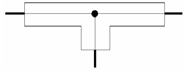
The most basic form of a power splitter is a simple "T" connection, which has one input and two outputs as shown in Fig. 2. If the "T" is mechanically symmetrical, a signal applied to the input will be divided into two output signals, equal in amplitude and phase. The arrangement is simple and it works, with limitations.
The two obvious limitations are poor isolation and impedance mismatch. First, let's consider isolation.
Suppose, for example, that two antennas were fed to a receiver input using a simple "T" as a combiner. If one antenna appears as a short at its resonant frequency, it would load down the other antenna and, in effect, wipe out the receiver input. However, a properly designed power combiner would provide high isolation between inputs so that the antenna "short condition" at one input would have little influence on the other input and would cause approximately a 3:1 VSWR mismatch at the output port, in this case, the receiver input.
In a simple "T" circuit power combiner the isolation between input ports will depend upon the impedance termination at the output port. If the output port is open then the input ports would have zero isolation between them. And, if the output port is terminated by a matched impedance the isolation would be 3dB.
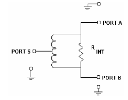
Improving upon the simple "T" circuit, consider the basic lumped element power splitter/combiner circuit of Fig. 3. The transformer has an equal number of turns from the center tap to each end. Therefore, as an auto transformer (2 to 1 turns. ratio) the impedance across the output ends is 4 times larger than the impedance across the center tap to one end.
Now, consider the second serious limitation of a simple "T", which still exists with the circuit in Fig. 3: impedance mismatch at the input.
In a 50-ohm system, each output would be connected to a 50-ohm impedance, thus offering a 25- ohm impedance to the input port. Thus, the impedance looking into the common or input port would present a mismatch in a 50-ohm system. To correct this mismatch, a 25 to 50-ohm matching transformer would be necessary as shown in Fig. 4.
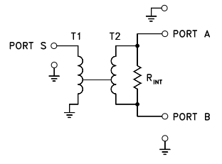
Let's examine how this circuit enables high isolation between ports A and B. As a power combiner, an input signal applied to port A will cause a current to flow through the transformer and experience a 180° phase shift by the time it arrives at port B. Similarly, a current will also flow through the resistor, R int and will not experience a phase shift by the time it arrives at port B. When R int equals the impedance value across the transformer ends then, the currents appearing at port B will be equal in amplitude but opposite in phase and cancel. The net result is that no voltage appears at port B from the input signal applied at port A. Thus, there is theoretically infinite isolation between the ports. Further examining the circuit of Fig. 4, let's determine the theoretical insertion loss between port S and ports A and B. As a power splitter, a signal applied at port S will be split so that identical signals appear at ports A and B, due to the circuit symmetry. If the impedance values are matched then maximum power transfer will take place and half the input power would appear at each port resulting in a 3dB theoretical loss at each port. Furthermore, under the conditions described the circuit is lossless since the voltage across R int is zero.
Let's take an example to illustrate the concepts described. Suppose we have a 50 ohm system so that ports A and B are each terminated in 50 ohms. They appear across the transformer in series so that a 100 ohm transformer impedance is required for optimum power match. Since the transformer has a 4 to 1 impedance ratio, the impedance at port S is 25 ohms. In this example we must add a 2 to 1 (50 to 25 ohm) transformer at port S so that the S port impedance is matched to the 50 ohm system. The connection of 2 to 1 transformer "T1" is shown on Figure 4.
Remembering the value of R int equals the transformer impedance (to obtain maximum isolation), R int equals 100 ohms. We have now completely specified the circuit values of the 50-ohm 2 way 0° power splitter/combiner.
Mismatch effect on isolation
Consider the ideal situation in a two-way power combiner where there is infinite isolation between the two input ports. A signal applied to port A will be routed to port S, minus a 3dB loss in the internal resistor; since isolation is perfect, none of the input signal will reach the other input port. Now, if port S is properly terminated, the sum signals will be absorbed and nothing will be reflected back to the input ports. Fine, as long as port S is properly terminated and thus no mismatch. Now, let's consider two examples of mismatch at port S, one slight and another large. Assume a + 20dBm signal is applied to port A; with perfect isolation, none of this signal reaches port B. Since there is a 3dB loss between input A and port S due to the loss in the internal resistor, + 17dBm arrives at port S ignoring any slight transformer loss. If a slight impedance mismatch exists at port S, which causes a -20dB signal reflection, then a signal of - 3dBm (+ 17dBm attenuated by 20dB) is sent back to ports A and B. This -3dBm signal experiences a 3dB loss as it is fed to port B, and the mismatch has now resulted in a -6dB signal at input B from port A. Now isolation between both input ports is not infinite; there is a +20dBm signal at port A and a -6dBm signal at port B for an isolation of 26dB. Reason? Slight impedance mismatch at port S.
What about a more serious mismatch? Suppose the + 17dBm signal arrives at port S and a mismatch produces a -10dB signal reflection. Now +7dBm is fed back to port B (+17dBm with 10dB loss); add the additional return 3dB loss, and a +4dBm signal appears at port B. Now isolation is only 16dB, the difference between port A's 20dBm and the 4dBm signal at port B due to the mismatch. Important point: make sure port S is properly matched to eliminate reflections and thus maintain high isolation. Mismatch at either port A or B is not critical if port S of a power combiner is properly matched. If cancellation through the transformer and internal resistor is taking place, there will not be any voltage drop across port A and B and thus no effect on isolation.
Let's take it one step further and assume port S and port A are properly terminated but port B is shorted. As a power combiner, port A would still be isolated from port B and "would not see the short at port B. "However, the impedance looking into the S port of the power combiner would be lower. As an example, for a 50 ohm power combiner the impedance at the S port would change from 25 ohms to 8 1/3 ohms as the termination impedance at port B changes from 50 ohms to a short.
Mismatch effect on insertion loss
For the power splitter of Fig. 4, consider the situation where one output port, B, is shorted. A signal applied to port S would result in half the power appearing at each port, A and B. Since port B is shorted, all the power appearing there would be reflected back into the power splitter. Half of this power reflected would be dissipated in the internal resistor and the other half would appear at port S. The power loss within the power splitter would therefore be 1/4 or 6dB below the signal power originally applied to port S. In a practical power splitter/combiner where R int does not exactly equal the impedance across the transformer, there would be less than a 3dB loss at port A because part of the reflected power from port B would appear at port A.
What limits the power rating?
The power handling capability of a power splitter/combiner is basically determined by the internal resistor across the transformer and the transformer's core and wire size. When used as power splitter, the core of the transformer may saturate at the lower frequency end of the operating band if the designated power rating is exceeded; signal distortion and reduction in isolation may result. At high RF frequencies, usually small diameter wire is used thus limiting the safe current level that can flow before failure. In a power combiner application, the power loss across the internal resistor must also be considered in addition to the transformer core effects. For example, in a 2 way power combiner, the internal resistor must be able to dissipate half the power applied to each port. The specifications for the internal load dissipation rating for each power combiner N way group is given on the individual specification pages.
If an application demands an internal resistor power rating larger than available as a standard catalog item, Mini-Circuits can supply a unit without an internal resistor. And a higher power rating resistor can be out-boarded. Of course, the performance of the final combination will depend on the external resistor's characteristics, the way it is wired, and its capacitance to the board on which it is mounted.
How to measure isolation
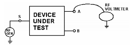
The isolation of the two-way splitter/combiner is obtained by measuring the attenuation between ports A and B when the common port is terminated in the correct value of impedance, generally 50 ohms. An RF generator signal is applied to port A and an RF voltmeter reading is taken at port B. The difference in dB represents the isolation between the two ports. When high isolations are encountered, in the range of 50dB, the accuracy of the measurement can be improved by replacing the RF voltmeter with a spectrum analyzer and/or by inserting a filter between the port A (or B) and the RF voltmeter. The filter reduces the effects of harmonics from the RF generator. This is especially significant when the isolation of the power splitter/combiner differs by more than 10dB over the frequency range covering the RF generator frequency and its harmonics.
The technique for measuring isolation of more than a two-way splitter/combiner is exactly the same as that just described; just make sure all unused ports are terminated with the appropriate impedance. However, the accuracy of this termination impedance is not very critical since there is usually high isolation between ports.
It is quite important, however, that the terminating impedance at the common or S-port be very accurate. Deviations from the correct impedance value will cause significant errors. Typically, a termination impedance with a VSWR of 1.05 to 1 is used at Mini-Circuits for isolation testing.
How to measure insertion loss
To measure insertion loss, first terminate all ports properly with 50 (or 75) ohm pads and then set the RF generator to the test frequency. An RF voltmeter reading is taken at port A and then at port S. The difference between the two levels, in dB, represents the insertion loss of the splitter. Repeat for ports B and S.
Although the above procedure is simple, the accuracy of the measurement is limited by the accuracy of the RF voltmeter. An improved technique requires a standard 3dB attenuator placed between test points A and S (see Fig. 5) with the two-way power splitter disconnected from the test set-up. The RF generator level is set so that the RF voltmeter reading is near the top of the scale, its most accurate region. Then, the 3dB standard attenuator is removed and the power splitter is connected to test points A, B and S. The difference between the first and the new RF voltmeter reading represents the additional power splitter loss over the 3dB theoretical value. Thus, the insertion loss is 3dB plus this incremental RF voltmeter reading. Repeat for port B. The procedure for measuring insertion loss for more than a two-way splitter is essentially the same as previously described. The difference is that the standard attenuator value should be close to the theoretical minimum insertion loss for the power splitter under test. Remember that all ports should be terminated in the correct value of impedance. Practically speaking, the terminations do not have to be perfectly matched but will influence measurement accuracy
Get tight specs at lower cost
Generally, engineering designs exist in a world of tradeoffs. Mixers, for example, can be designed so that isolation can be improved at the expense of conversion loss; similarly, an amplifier's noise figure can be improved if a reduction in dynamic range can be accepted in exchange.
Not so, fortunately with power splitters. The key parameters are influenced in the same direction during the design stage. A well-designed power splitter/combiner will offer high isolation, low insertion loss and good VSWR. You just don't encounter a power splitter/combiner with high isolation and poor VSWR, nor high isolation with a poor insertion loss spec. Why? Because poor insertion loss specs generally result from an improper matching transformer (winding not exactly symmetrical) or slight variations in stray capacitances at each end of the transformer; these effects, however, adversely affect insertion loss as well as isolation.
This raises a significant point. There is no need to specify a number of tight spec parameters when you need a power splitter/combiner for a particularly stringent requirement. Simply specify a tight improved spec on the key parameter most critical to the task and you'll find the remaining specs will also be upgraded. If you insist on writing tight specs on a number of parameters, you may be paying extra money for a device you would have received anyway. Of course, you can specify one tight parameter, as suggested, and request support data on the other parameters to monitor their characteristics.
In some applications, it is possible for several parameters to be important. In other applications, only one parameter may be considerably significant while others are not. For example, in a power combiner used to add the outputs of two amplifiers, insertion loss is a critical factor while isolation may not be deemed essential. On the other hand, consider a test setup for two-tone, third-order IM measurement. Here it is common to operate two RF generators that are close to each other in frequency, resulting in one generator "talking to the other" or "pulling". To avoid this measurement pitfall, a power combiner is placed between both RF generators; here the isolation spec is very significant while other parameters, such as phase or amplitude unbalance, have no importance at all. You can lower your demands, and your cost, by analyzing what parameters must be met while understanding others that can be ignored.
