Soldering Turret Terminal Pins on ZX series models
1. Introduction:
The following application note is a guide for soldering wire connections to Turret Pin Terminals on the Mini-Circuits ZX series Amplifier, Power Detector, Voltage Variable Attenuator, Digital Step Attenuator, RF Switch, Bias-Tee, and VCO models. The information below is intended to ensure proper soldering of wire connections to the turret terminals on the Mini-Circuits models while maintaining optimum reliability.
Mini-Circuits does not recommend use of temporary connections to the terminal pins such as alligator clips, however, in terms of convenience, there is often no replacement. If temporary clips are used ensure use of insulated clips to prevent short circuit between terminal pins or to case ground.
Wire wrapping and soldering criteria is covered by various electronics assembly standards, the following information is based on the IPC-A-610D Standard, Acceptability of Electronics Assemblies and the NASA Standard, NASA-STD 8739.3, Soldered Electrical Connections. Please note that electronics assembly standards sometimes conflict, please review to ensure your finished assembly will meet the applicable Standard for your Application.
2. Soldering Guideline:
2.1 Soldering Equipment Used
Soldering irons shall be of the temperature controlled type, controllable within ±5.5°C (±10°F) of the selected temperature.
a. Use the lowest soldering temperature that will give you a properly wetted solder connection between wire and terminal. When using a Lead-Free solder (melting point ~220°C), we recommend a maximum solder iron tip temperature of 350°C. When using a Tin/Lead solder (melting point ~180°C), we recommend a maximum solder iron tip temperature of 300°C.
b. Solder heating duration should be less than 5 seconds.
2.2 Hookup Wire
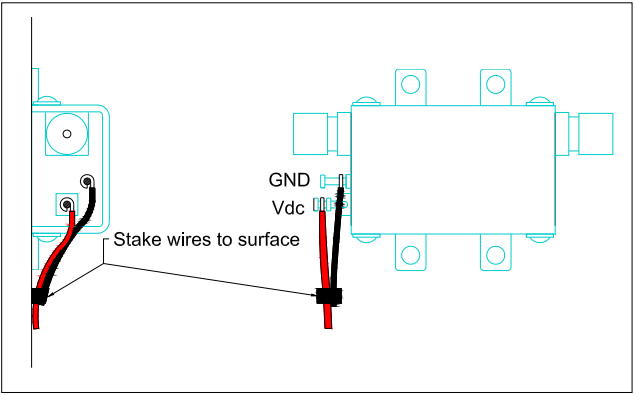
1. Hookup wire, solid or stranded, should be supported by a means other than the solder connections (i.e. make sure of staking as means if creating a stress relief).
2. Use of thin Hookup wire is best to minimize stress on the terminals, Mini-Circuits recommends the following maximum wire sizes:
a. For multi-strand wire, #22 AWG (7x30 stranding).
b. For single core soft copper wire, #28 AWG.
The minimum wire size should be based upon DC current requirements, which are specified in the individual model data sheet.
2.3 Assembly Procedure
1. Wire leads should be tinned and formed before mounting on the terminal.
2. The insulation clearance shall be less than two wire diameters, including insulation, but in no case shall permit shorting between adjacent conductors.
3. Hookup wire should be wrapped and confined to the guide slots on the terminal.
4. Hookup wire may be wrapped clockwise or counterclockwise on the terminal and shall continue the curvature of the dress. The curvature of the dress shall not exceed 20° from a perpendicular line from the last point of contact between the wire and terminal (as this will introduce a Stress at the solder termination and terminal).
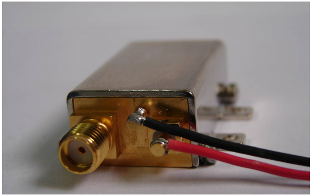
5. See Diagram and Photo below for reference.
NOTE: Published Assembly Standards present conflicting information regarding wire wrapping around the terminal, e.g.
- Per IPC-A-610
- Wrap wire larger than #30 AWG a minimum of 180° and a maximum of 270°.
- For # 30 AWG and smaller, wrap wire two times (720°) around terminal post and a maximum of 3 times, wire does not overlap or cross over itself on the terminal.
- Per NASA-STD 8739.3
- Wrap wire larger than #26 AWG a minimum of 180° to a maximum of 270°.
- For #26 AWG and smaller, wrap wire a minimum of 180° but less than 360
Mini-Circuits recommends following the IPC-A-610 Standard as this is the generally accepted world-wide assembly standard for commercial applications.