SURFACE MOUNT ASSEMBLY OF MINI-CIRCUITS COMPONENTS
1.0 Introduction
Mini-Circuits has a long history of manufacturing high quality surface mount components in a variety of:
- Shapes and sizes
- Monolithic and hybrid
- Leaded and leadless
- Open structure and encapsulated
- RoHS compliant or SnPb (tin/lead)
- Aqueous washable, hermetic, or no-clean
- Active and passive
While all surface mount parts are designed to meet industry standards for SMD assembly, the wise customer will understand that variations in process and materials need to be accounted for when developing an assembly method. Customer qualification of processes is essential to ensure that one gets the most out of any surface mount assembly product.
This article is intended as a primer to assist the customer in his development of an efficient and controlled process of automated solder stenciling, component population, reflow and cleaning.
2.0 Layout Design
The Mini-Circuits Model Datasheet specifies a “PL” layout drawing to be used with each model. This layout is designed to provide the optimum performance in keeping with industry standards for pad dimensions, substrate materials, PTHs, and proper grounding. In some situations, values of biasing components are included as well.
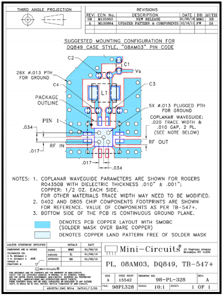
Failure to use the specified layout may result in the device not meeting the specified performance. Customers with limitations on their ability to follow this layout should contact our Applications Engineering group for assistance in creating a ‘special’ design.
3.0 Solder Selection and Stenciling
Mini-Circuits surface mount components are designed to be compatible to a wide range of solders offered in the industry. Our RoHS compliant components are also reverse compatible to SnPb (eutectic) solders.
The preferred method and solder for automated surface mount assembly is reflow using solder paste. Solder paste comes in a variety of formulations and bead sizes that can be matched to the customers equipment and process conditions. Wherever possible, we strongly recommend the use of no-clean solder with a lowest melting temperature and time above liquidus.
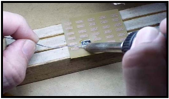
Although not recommended as the first option, many of Mini-Circuits surface mount products can be manually soldered by a skilled operator using a calibrated soldering system. This is certainly the case with leaded devices or parts with castellated wraparound terminations. Care must be taken to avoid overheating the parts and applying too much solder.
Stencils are required when using solder paste in its intended method. All Mini-Circuits surface mount devices are specified to 4 mil coplanarity. Stencil design should include the solder thickness, aperture (or amount of the pad to be covered), and internal cut angle for best release. Proper maintenance, including regular stencil cleaning, is required for optimal results.
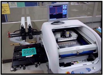
4.0 “Pick and Place”
Mini-Circuits’ surface mount products are available in EIA compliant carrier tapes for automatic ‘Pick and Place’ population using a variety of high speed machines available on the market. Our datasheet identifies the “Tape and Reel” specified for each model. This includes device orientation within the pocket and number of units per standard reel.
Mini-Circuits has also introduced ‘Small quantity standard reels’ to enable customers to efficiently and economically use ‘less than complete reel’ quantities with required leader and trailer for pick and place. Customers with special reel quantity requirements, not cover by our standard or ‘small’ quantity reels, can contact customer support for pricing and availability.
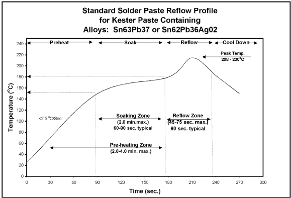
5.0 Reflow
Perhaps the most frequently asked question received is “please tell us the recommended reflow profile?” This is a case where the answer is more easily done than said. Establishing a reflow profile is not a ‘one size fits all’ situation.
Among other considerations, the determination of an ideal profile is dependent on:
- The capabilities and zone structure of your oven
- The specified requirements of your solder supplier
- The device location, density and heat distribution of your panel
- The type of devices being assembled on the same PWB (ex: fine pitch, large mass, physical geometries)
- Termination platings
- MSL of devices
Mini-Circuits components are labeled with the “e” code identifying plating per JESD97 standard. Our components are capable of withstanding the precondition reflow profile as specified in J-STD-020. This having been said, however, does not mean to imply that the extreme conditions in the J-STD-020 are intended for production assembly use.
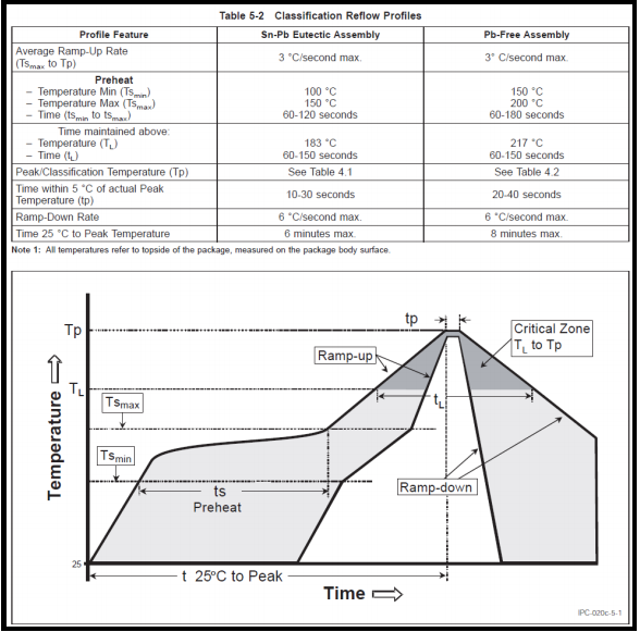
Selecting the proper profile requires a controlled evaluation process beginning with the use of the profile recommended by the solder supplier. Tweaking or adjustments to this are to be done by trained process engineers or technicians, and properly documented.
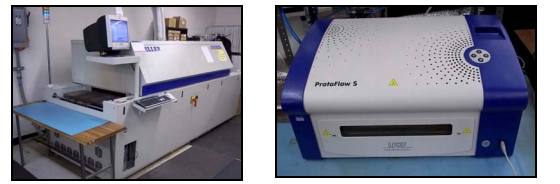
While most mass production reflow is done in conveyor ovens with multiple zones for smooth temperature transitions, there are several table top stationary ovens that are capable of consistently reproducing profiles for small lot or prototyping.
Whichever system or solder formulation is used, this must include a documented program of inspection and, if needed, rework.
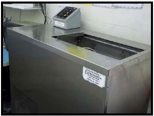
6.0 Cleaning
Customer cleaning is the process with most variations and the activity for which Mini-Circuits has the least control. Among the variations we have seen are:
- Solution used
- pH range: acidic, neutral, alkaline
- Cleaning equipment: vapor degrease, water wash, ultrasonic vibration
- Conditions: time duration, temperature, vibratory settings
- Drying
- Handling of parts while cleaning
All the above have a direct impact on the initial quality and reliability of the customer assembly process and must be documented and controlled.
Mini-Circuits recommends use of pH neutral cleaning solutions. Other solvents, especially high pH solutions are not to be used. High alkalinity solvents are corrosive and can have long term effects, especially if not properly neutralized or dried.
Similarly, ultra-sonic vibratory cleaning is not recommended, or must be used with extreme care. The military and aerospace industries have prohibited use of ultra-sonic cleaning for many years. Devices with internal wire assemblies can be damaged by this process. IPC-CH-65 is a good guide to cleaning of electronic assemblies.
Use of no-clean solders is an industry accepted method of reducing the need to do aggressive cleaning that can lead to product damage.
7.0 Summary
Mini-Circuits designs quality and robustness into all our products. Our product lines have a long history of acceptance in the industry. Our expectation is that customers will use proper process verification controls in qualifying and assembling these parts in their systems.
