Automated Load Pull Measurement of Voltage Controlled Oscillators
Introduction
Voltage Controlled Oscillators (VCOs) are normally designed for operation into ideal 50 ohms impedance. Actual loads into which they work are seldom ideal. It is a standard industry practice to measure the variation of the frequency when the VCO output is seeing a load with 12-dB return loss (for all possible phase angles). This is normally done as a manual measurement and is very time consuming. A skilled technician may take minutes to hours. Mini-Circuits has developed an Electronic Line Stretcher, which can be used to automate these measurements.
Traditional method
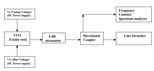
Fig. 1 shows the block diagram of the manual measurement setup. RF output of the VCO is connected through a 6 dB pad and a Directional Coupler to a loss-less line stretcher. The signal for frequency monitoring comes from the Directional Coupler to the Frequency Counter or Spectrum Analyzer. The line stretcher should be capable of providing 360° phase shift over the entire frequency of operation of the VCO. During measurement, VCO is biased with Vcc power supply. The tuning voltage, Vt is fixed at a particular voltage. Then the line stretcher is manually tuned to cover the 360° phase shift. The maximum and minimum frequencies are measured and recorded. The difference gives the frequency shift due to load pull. This measurement is repeated for various tuning voltages applied to the VCO. If more devices need to be tested, this entire procedure is repeated for each device.
Drawbacks of traditional method
It is feasible to get a mechanical line stretcher, which can provide 3600 phase shift, at frequencies above 1000 MHz. At low frequencies, it is very difficult to get a continuously variable mechanical line stretcher. In order to overcome this, "short" or "open" technique and fixed lengths of transmission lines are added to a high frequency line stretcher. For example, let the mechanical line stretcher cover a 360° phase shift at 1000 MHz. If the oscillator carrier frequency is 500 MHz, the same line stretcher covers only 180° . To do the load pull measurement, first the frequency extreme search is done for 1800 continuous phase shift range when the line stretcher has an "open" on its end. Then, the "open" is replaced with a "short", which provides extra 1800 phase jump, and the other frequency extreme search is repeated. The minimum and maximum oscillator frequencies obtained from both the measurements is noted and used to compute the load pull. At 250 MHz, the measurements need to be done in four steps. At each step, an "open-short" technique and additional quarter wavelength line, which provide extra 900 phase jump, have to be applied. In addition the test engineer needs to consider the added insertion loss of the line stretcher itself, actual losses of directional coupler and additional transmission line losses and reduce the fixed attenuator value. As is evident from this example, the procedure is very cumbersome.
Conventional electronic phase shifters can be used, but are generally narrow band and their insertion loss varies with phase shift. One needs to be careful about saturation effects in the phase shifter, and operate much below saturation. In order to improve this situation, Mini-Circuits has introduced wideband, full phase range Electronic Line Stretches to greatly improve upon the electronic method.
Electronic Line Stretcher
Mini-Circuits has introduced a series of Electronic Line Stretchers to cover the frequency range of 110 to 1300 MHz. These Electronic Line Stretchers are three-port devices. They provide a nominal return loss of 10 to 12 dBr. The phase variation exceeds 360° within specified operating frequency range and can be electronically controlled. A sample of the oscillator RF signal, used for frequency measurements, is available at the Monitor Port.
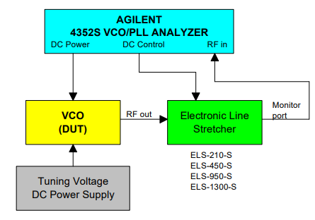
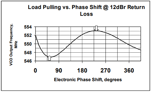
These Electronic Line Stretchers are used in automated setups as shown in Fig. 2. The output of the VCO is connected to the "RF IN" port of the Electronic Line Stretcher. The RF signal from the Monitor Port of the Electronic Line Stretcher is connected to the RF input of the AgilentTM VCO/PLL analyzer. DC control voltage from the VCO/PLL analyzer is connected to the Control Port of the Electronic Line Stretcher. As the DC control voltage is swept from 0.5 to 25V, the phase angle of the load presented to the VCO is changing by more than 360°. The VCO/PLL analyzer is set to display frequency vs. DC control voltage (which represents a phase variation of the load). The peak to peak difference in the displayed frequency gives the load pull. Fig. 3 shows an example. The x-axis is Electronic Phase Shift, which is a function of sweep voltage applied to the Electronic Line Stretcher.
Performance of Reflection Line stretcher
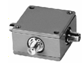
Fig. 4 is a photograph of the Electronic Line Stretcher. It is housed in a connectorized case and has female SMA connectors on all ports. The housing size is 1.25"x1.25"x0.75". The return loss is designed to be 10 to 12dB. The reason is that most VCOs are specified to operate at 12 dB return loss. By maintaining the return loss in the range of 10 to 12 dB, the measured load pull will be conservative. The phase angle of the reflected signal is at least 3600 over the specified frequency range.
Conclusion
A set of four Electronic Line Stretchers has been introduced. Aim of these devices is to automate load pull measurements of oscillators.