Test Report for Mating Cycle Validation of Mini Circuits QBL Series Quick-Lock Test Cables.
Background & Introduction
Mini-Circuits has introduced a QBL Series of test cables is based upon an industry-unique Quick Lock Connector which enables a quick, secure locked connection directly to a standard SMA female jack. This high integrity connection enables users to connect to an SMA Jack without the need for twisting and torqueing as with any normal SMA connector, making it ideal for test applications.
In test applications, the number of cycles becomes of significant importance, although standard mating cycle testing is limited to 500 cycles (per mil-spec), in an RF test lab environment it is possible that this number of actual insertions can far exceed this standard and therefore validation of this new interconnect system at higher mating cycles is performed by Mini Circuits.
Purpose
The purpose of this experiment is to establish baseline performance over a large number of mating cycles for the new Quick Lock interconnect system up to a maximum of 20,000 cycles. The basis of this extended reliability and qualification standards apply to all products including laboratory testing cables.
Scope
QBL Series Quick Lock interconnect cable assemblies.
Conclusion
All 5 samples tested meet or exceed product specifications up to 20,000 cycles and meet or exceed acceptable limits of degradation over same period.
Test Apparatus & Setup
Description of Device under test:
- Mini-Circuits Quick-Lock connector (Fig.1)
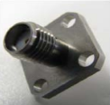
- Standard SMA Connector (Stainless Steel Jack) (Fig.2)
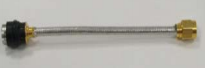
- DUT (Test Cable Assembly) (Fig.3)
- Test Setup
- Insertion of the Quick Lock Connector on the fixed SMA Male Connector.
- Engagement of the Quick Lock locking push-on shroud.
- Dis-Engagement of the Quick Lock locking push-on shroud.
- Extraction of the Quick Lock Connector from the fixed SMA Connector.
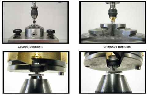
As outlined in Figure 4, a custom test fixture insertion assembly was developed to engage the DUT, (see Figure 4) at the Quick Lock connector end of the assembly and execute a quick lock connection to a standard SMA stainless steel jack which is fixed in the test jig.
One (1) insertion cycle includes:
This sequence was repeated for 4 sets of 5,000 cycles with validation testing at each interrupt. See test sequence below

Test Sequence
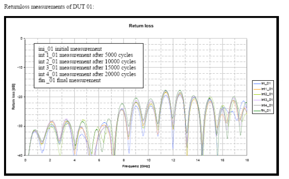
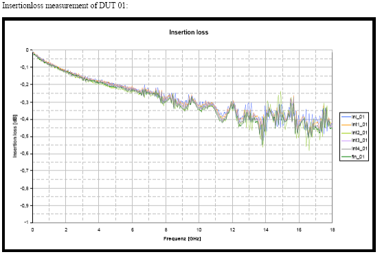
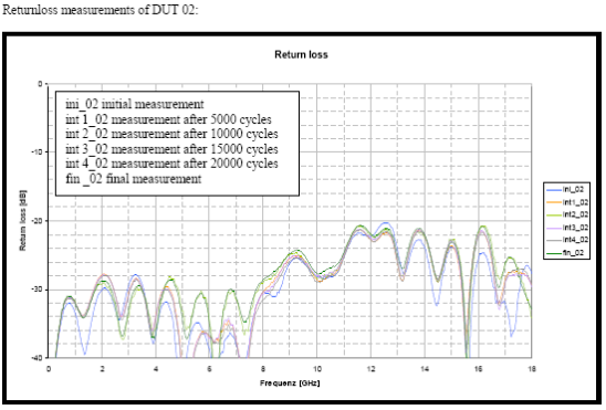
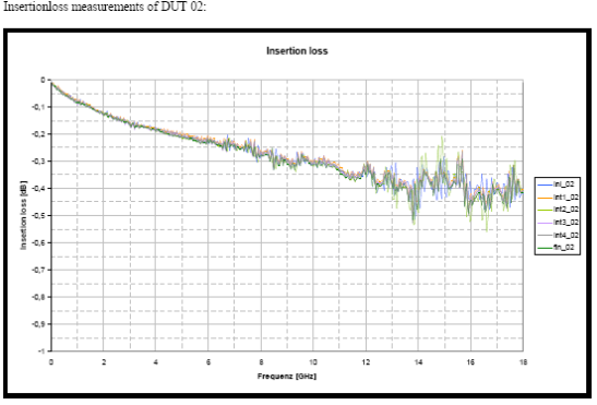
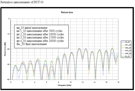
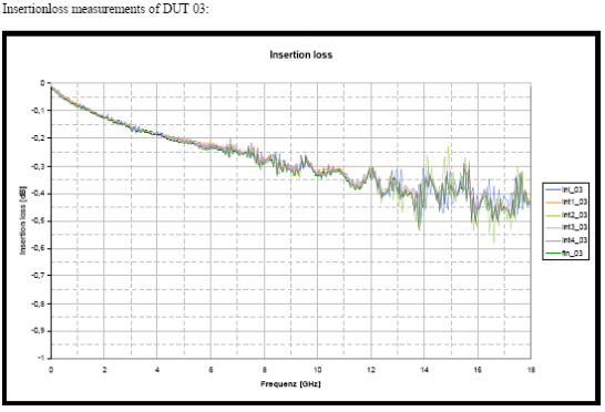
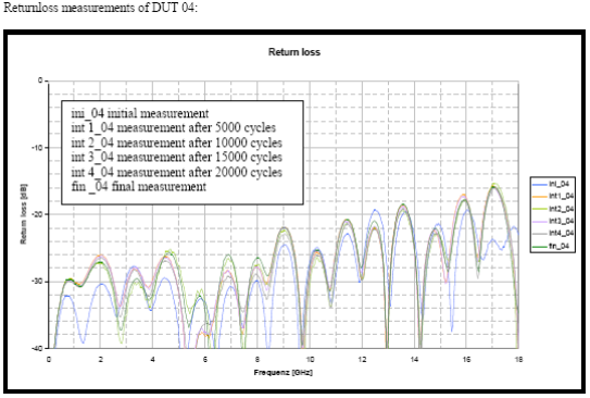
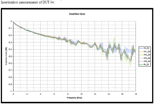
- Five (5) DUT Cable Assemblies prepared for Mating Cycle Test. Pre Test Sweep from DC to 18 GHz, S Parameters compared to DUT Specification
- DUT No. 1 Mounted in Test Fixture
- Perform Mating Interconnection - 5000 Mating Cycles
- Dismount DUT and Sweep from DC to 18 GHz, S Parameters compared to DUT Specification and previous measurements
- Perform Mating Interconnection - 5000 Mating Cycles (10,000 total cycles)
- Dismount DUT and Sweep from DC to 18 GHz, S Parameters compared to DUT Specification and previous measurements
- Perform Mating Interconnection - 5000 Mating Cycles (15,000 total cycles)
- Dismount DUT and Sweep from DC to 18 GHz, S Parameters compared to DUT Specification and previous measurements
- Perform Mating Interconnection - 5000 Mating Cycles (20,000 total cycles)
- Dismount DUT and Sweep from DC to 18 GHz, S Parameters compared to DUT Specification and previous measurements
- REPEAT for DUT No.2 through DUT No.5
Test Results