Mini-Circuits PWR-6GHS+ USB Power Sensor
For much of my homebrew work I need to accurately measure RF power. And I need quite a large range - from low levels such as the output of an oscillator, mixer or coupler, to the much higher output of typical amateur transceivers from HF through UHF. Most available ham type power meters aren't precision instruments, and those that are accurate don't satisfy my low level measuring requirements. So what to do?
Enter the Mini-Circuits PWR-6GHS+
While doing an Internet search on RF power sensors, I stumbled across the MiniCircuits PWR-6GHS+. This USB powered RF power sensor measures average signal power levels from -30 dBm to +20 dBm in the 1 MHz to 6 GHz frequency range. It's calibrated, and it uses your computer and supplied software for the display. While it may seem pricey at $795, it is lower in cost than a used, calibrated commercial power meter. The PWR-6GHS+ comes with a one year warranty and can be recalibrated by Mini-Circuits for $99 if desired.
The PWR-6GHS+ measuring system consists of the power sensor, a male type N connector, an N-to-SMA adapter, a USB interface cable, the installation software CD and the user manual. The basic specifications are shown in Table 2, along with results of some ARRL Lab testing.
Mini-Circuits offers two other versions of the USB power sensor: the PWR-6G+ and the PWR-8GHS+. The PWR-6G+ has a slightly slower sampling speed and is limited to Windows 32 bit operating systems (XP, Vista and Windows 7) - no Linux or 64-bit Windows support. The PWR-8GHS+ has the same specifications as the PWR-6GHS+ except the frequency range is extended to 8 GHz. At $695, the PWR-6G+ is $100 less expensive than the PWR-6GHS+; the PWR8GHS+ is $869.
Using the PWR-6GHS+
The latest software is available on the Mini-Circuits Web site for easy download and installation. In addition to reading and displaying RF power, the software also provides text file and Excel spreadsheet file outputs, maximum/minimum measurement limits, and time scheduled measurements with a power output versus time graph. You can even add additional power sensors to other USB ports, and the software will read and record the data from all sensors simultaneously.
For maximum accuracy the measuring frequency is entered in the display window. You don't need to change the frequency input unless you move more than 100 MHz. An internal temperature sensor in the PWR-6GHS+ also provides for temperature variation compensation to keep the readings accurate. Now let's look at some power sensor applications.
Calibrating Attenuators
With an input power range from -30 dBm to +20 dBm, you will require attenuators for power levels above 100 mW (+20 dBm). All attenuators I've looked at have well-controlled return loss and attenuation across the bandwidth I need (1.8 to 450 MHz). The attenuator specifications, however, are typically ±0.3 to ±0.5 dB about their nominal attenuation value. This sounds good, but ±0.5 dB corresponds to about a 12% error, and ±0.3 dB corresponds to about a 7% error. So a transceiver that puts out exactly 100 W could measure as little as 88 W or as much as 112 W with a ±0.5 dB attenuator specification. If you cascade attenuators, you can cascade the attenuator errors making them much worse (or much better) than this. Of course, the PWR-6GHS+ has a typical measurement uncertainty of ±0.1 dB. But with a little care, you can calibrate your attenuators so that your total uncertainty is no more than this.
For attenuator calibration you need a stable low level signal source. Most antenna analyzers have output levels that can be used. For attenuator calibration you need a stable low level signal source such as is available from most antenna analyzers. As examples, the nominal output levels of the Array Solutions AIM 4170C and VNA 2180 are -18 dBm and +7 dBm, respectively. The nominal output levels of the RigExperts AA-200/230 and the MFJ-259B are +10 dBm. The actual measurement frequency is usually not important, as most attenuators you buy are specified into the microwave range and the attenuation is usually very consistent across the full range. For most amateur applications, a test frequency of 50 or 100 MHz works very well.
Calibration Procedure
For high power applications, I use a 20 dB, 150 W attenuator and a 20 dB, 2 W attenuator for typical 100 W transceiver measurements. I also have a variety of 10, 6 and 3 dB attenuators for flexibility in measuring various power levels.
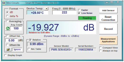
Because of the "relative" measuring capability of the PWR-6GHS+, the actual output power of the signal source is unimportant - as long as you don't exceed the maximum input power. Simply connect the PWR-6GHS+ directly to your low level frequency source and check the RELATIVE and dB boxes on the display. Now anything connected between the PWR-6GHS+ and the signal source reads out exactly in dB.
To illustrate the calibration process, I wanted to accurately measure the output power level of my Jetstream JT220M 222 MHz transceiver. While I used my RigExperts AA-230 with a 10 dB attenuator as the signal source for calibration. Figure 3 shows the actual measured attenuation of my high power attenuator
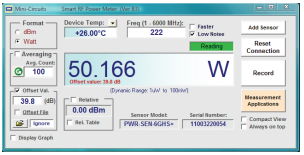
Using the same procedure, I measured my 20 dB, 2 W attenuator at -19.872 dB, giving a total attenuation of 39.8 dB. Now enter the 39.8 dB total attenuation in the OFFSET VALUE box. You can now read the output of the transceiver directly in watts as you can see in Fig-ure 4. The measured output power of 50.166 W is very close to the JT220M specified typical output power of 50 W. Incidentally, I was able to mount the attenuators and PWR-6GHS+ directly to the JT220M RF output connector. If you use an interface cable, you may need to add in 0.1 to 0.2 dB additional cable losses for best accuracy.
Measuring Return Loss
Many hams have an antenna analyzer that permits measurement of SWR up to about 170 to 200 MHz. Measuring above this frequency range normally means investing in much more expensive equipment. Of course, the reason you'd need to measure SWR above 2 meters is because you have a 222 or 440 MHz radio, so you do have a signal source - your transceiver. With that signal source, you can measure return loss using a broadband directional coupler. I found that the relatively inexpensive Mini-Circuits ZFDC-20-5N coupler ($90) is perfect for virtually all of these applications. This coupler is specified from 100 kHz to 2 GHz with a maximum input power of about 2 W, so you do need to size your attenuators appropriately.
To illustrate, I wanted to see how well a 1 /4 wave 147 MHz antenna might work at 445 MHz, at which point the antenna is a little less than 3/4 wavelengths. I measured a 1.5:1 SWR at 147 MHz using my antenna analyzer, which corresponds to a 14 dB return loss. To measure return loss at 445 MHz, I used the test setup shown in Figure 5. Note that we're feeding the signal into the output (OUT) port of the directional coupler. This is correct, as we want only the reflected signal from the unit under test to couple out to the PWR-6GHS+. In other words, the reflected signal becomes the input to the directional coupler, as we're measuring the "loss" of the "return" signal - return loss!
The 20 dB attenuator limits the signal into the coupler to about 0.5 W. First I left the IN port of the coupler open so all power is reflected, resulting in a measured reflected power level of +6.49 dBm. Precise measurement of the attenuators, coupler, transmitter output power and cable loss is not necessary as we only need relative readings for the return loss measurement. However, the numbers make sense: 50 W = +47 dBm. Less 20 dB attenuator = +27 dBm. Less 20 dB coupling of the reflected signal = +7 dBm (close to the measured +6.49 dBm). This is well above the -30 dBm threshold of the PWR-6GHS+, which gives us a good return loss measurement range.
Now check the RELATIVE and dB boxes on the PWR-6GHS+ display to set this as the reference reflected power level and then connect the antenna to the IN port of the coupler. As you can see in Figure 6, the return loss of the 147 MHz antenna at 445 MHz is 6.6 dB, or about a 2.8:1 SWR. This is not great, but it is within the load range of many UHF transceivers.
Final Thoughts
I've described some basic measurements that are easily accomplished with the Mini-Circuits PWR-6GHS+ USB power sensor. I'm sure other applications will come to mind as you work with this instrument. Obviously you can measure coupler directivity (OUT to CPL with IN terminated on the Mini-Circuits ZFDC-20-5N). And because of its wide and linear dynamic range, you could use the PWR-6GHS+ and a low level variable frequency source to measure filter performance (insertion loss, shape factor, in-band ripple, ultimate rejection and return loss). It's a very flexible instrument indeed!
Because your laptop takes care of all display information, no other external equipment is required other than the power sensor head - even if you need multiple sensors and data recording. You can view detailed documentation for these power sensors on the Mini-Circuits Web site.