Ultra-Linear 32W Amplifiers 500-1000MHz (LZY-2)
General Description
The LZY-2+ is a low cost, rugged, versatile, 40dB Gain (minimum), Broadband, Class A Linear RF Power Amplifier designed to operate linearly over the 500MHz to 1000MHz frequency band. The LZY-2+ features low compression and low harmonic distortion at 20 watts, which make it ideally suited to a wide variety of AM, FM, Pulse and Multi-Carrier applications including cellular service in FEEDFORWARD amplifiers as a Pre Amplifier, Main Amplifier or Error Amplifier.
The conservative electrical and thermal design and careful attention to semiconductor ratings ensures continued years of service in both the laboratory and many Commercial and Military environments.
The workmanship, quality and attention to protective features, along with selection of components to COTS (commercial off-the-shelf) guidelines, further enhance applicability and long MTTF which results in low cost-of-ownership.
The unit electrical performance is specified at +28VDC, but the unit will operate without damage over the range +24VDC to +30VDC.
The LZY-2+ is supplied with its own high thermal efficiency heat sink and 4-inch ball bearing cooling fan for immediate use and reliable operation.
For applications where the heat-sink and fan assembly presents a difficult physical fit, Model LZY-2X+ offers the same RF linear amplifier as a module without the heat sink and fan assembly. The user of LZY-2X+ is responsible for providing adequate alternative heat-sinking and/or cooling, following the guidelines in section 8.0 of this application note. If you have purchased LZY-2+ and want to use it as LZY-2X+, the module may be removed and operated safely with alternative heat sink and/or cooling methods if the guidelines in paragraph 8.0 are followed. Operation of the amplifier module without proper heat sinking and/or cooling is not recommended and violates the warranty. Discussion of LZY-2+ function and performance in this application note applies equally to LZY-2X+.
Protective features such as Input Overdrive, Reverse Polarity, Transient Protection and Thermal Overload with automatic reset are included. A separate shut-off terminal is provided for remote amplifier on/off control.
The LZY-2+ was designed to satisfy a range of broad and narrow band multi-tone or single frequency applications for original equipment, production test and laboratory equipment uses.
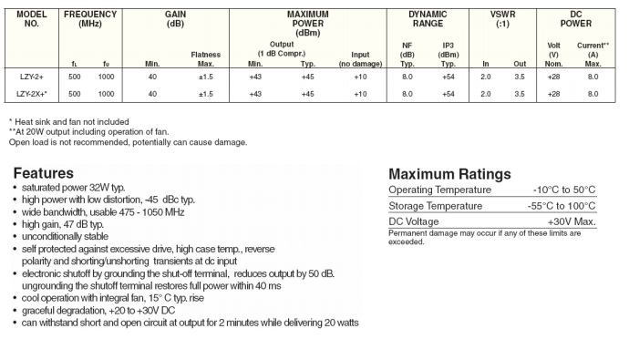
Electrial Performance Specifications
The Electrical Performance Specifications and limits are listed in Table 1.
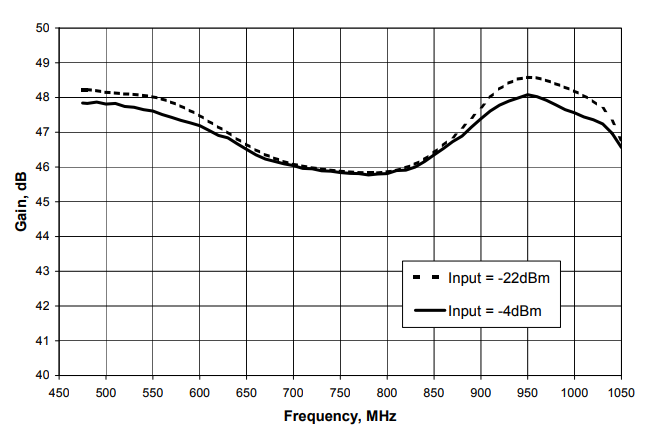
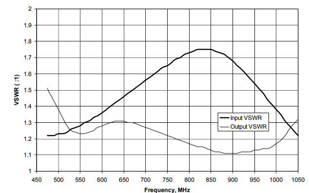
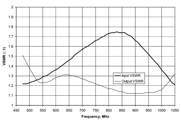
Typical broadband small-signal gain (-22dBm input) and large-signal gain (-4dBm input) are plotted in Figure 1. Similarity of the gain curves indicates dynamic linearity of the LZY-2+ across the frequency band. Input and output VSWR responses for small signal and large signal are shown in Figures 2a and 2b respectively.
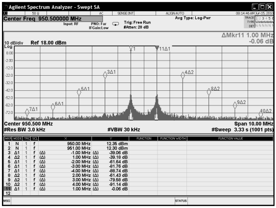
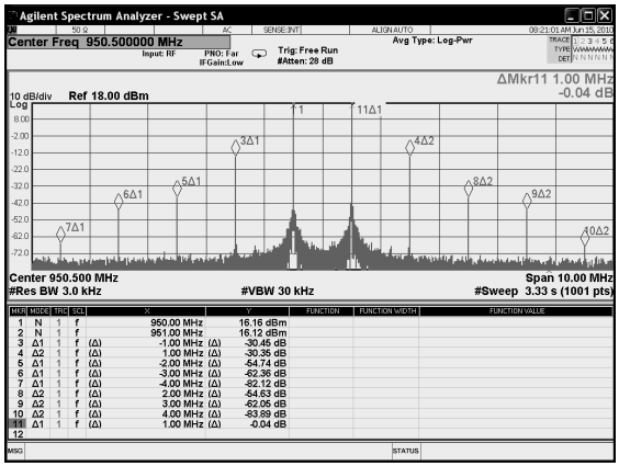
Figure 3 illustrates two-tone intermodulation performance with tones separated by 1MHz at 950.5MHz center frequency: 2W output per tone in Figure 3a, and 5W output per tone in Figure 3b. IP3 values calculated from the spectrum analyzer displays are +52.6dBm and +52.2dBm respectively.
Mechanical Specifications
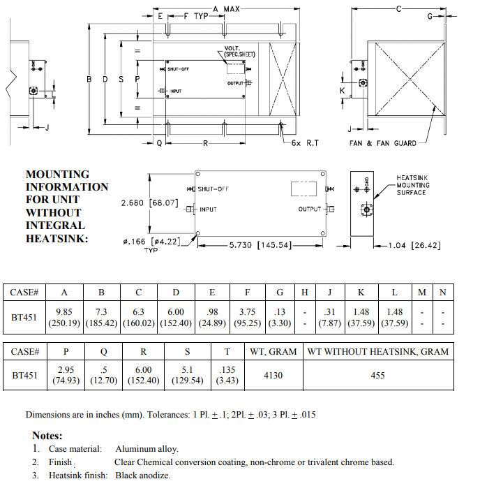
The mechanical outline drawing, mechanical specifications and heat sink mounting details are shown in Figure 4.
Electrical Features
Overdrive Protection
The LZY-2+ is designed to operate with input drive levels up to +10dBm without damage at any frequency in the 500MHz to 1000MHz range.
The unit contains a factory set control for automatic power output foldback to protect internal components from RF input overdrive damage.
Foldback action takes place when the input drive level exceeds a threshold. At threshold, the output power begins to drop. As input drive level is increased, the output power turns down to a low level, safeguarding the amplifier components.
At input drive levels below the threshold, the overdrive protection circuit is inactive and does not affect amplifier performance. The unit will perform within the limits of the specifications of Table 1.
Thermal Overload Protection
The LZY-2+ has an automatic built-in thermal shutoff feature. When mounted on the heat sink / fan assembly supplied with the unit, the LZY-2+ is a thermally efficient system that meets the performance parameters in Table 1 in ambient environments from -10°C to +50°C.
The amplifier is factory mounted on the heat sink using a thin film of thermal grease between the RF module and the heat sink mounting surface. (See paragraph 8.0 for operation without the factory supplied heat sink.)
With the fan operational at +28 VDC, the cooling air velocity is approximately 110 CFM.
The combination of heat sink design and cooling air velocity results in a very efficient thermal resistance (0.08°C/watt) between the mating surfaces. Under these conditions, the amplifier temperature is about 15°C above ambient temperature at 20 watts POut.
When the temperature of the LZY-2+ exceeds +65°C due to any combination of ambient temperature and / or overdrive, a thermal switch will actuate and shut off the amplifier by shutting off bias to all stages. As the amplifier case cools down near 40°C, the thermal switch will reset and restore the amplifier to normal operation.
Reverse Polarity Protection
The LZY-2+ is protected against damage from improper connection of the supply voltage by incorporating a diode in series with the positive VDC terminal.
Transient Protection
The LZY-2+ is protected from damage by DC line transients and accidental shorting at the VDC terminals.
Shut-Off Terminal
The LZY-2+ has a separate EMI-Filtered shutoff terminal and a corresponding ground terminal for use with an external remote shut-off circuit.
The nominal RF power output of 20 watts is reduced by 50dB minimum within 20 milliseconds when the shut off terminal is grounded.
When the shutoff terminal is open-circuited, the RF output is restored within 40 milliseconds.
General Precaution
The LZY-2+ is designed to operate over the 500MHz to 1000MHz frequency band.
Do not apply out-of-band RF power signals to this unit below 475MHz or above 1050MHz. Attempted operation out-of-band could result in damage or failure of the unit caused by imbalance of the Quadrature Combined Output Transistor Stages.
Mechanical Features
OUTLINE
The outline drawing and dimensional detail are shown in Figure 4, above.
Heat Sink
The LZY-2+ heat sink is a high thermal efficiency heat sink that, when used with the 4-inch 110CFM fan, results in a thermal resistance of 0.08°C/watt. (See paragraph 4.2 for other thermal considerations).
Cooling Fan
The cooling fan is a long life, brushless DC-operated 4-inch ball bearing fan which delivers 110CFM air at +28VDC. The fan is mounted to an optimally designed plenum on the heat sink for minimum air turbulence. The fan is protected by a fan guard.
The DC requirement of the fan, as installed, is 300mA typical, 400mA max at +28VDC.
The fan meets EMI standards per FCC Part 15, Subpart J.
Weight
The LZY-2X+ amplifier module alone weighs less than 1.14kg. Total weight of LZY-2+ with heat sink and fan is less than 4.0kg.
Suggested Applications (General)
The following performance characteristics are those generally expected from the LZY-2+ under the conditions stated for each application. The versatility of the LZY-2+ ultralinear amplifier is denoted in each of these applications for AM, FM, Pulse, Multi-Carrier and other signal formats and modulation schemes in applications within the 500MHz to 1000MHz frequency spectrum.
The suggested performance is provided to the user as an applications guideline which makes the LZY-2+ ideal for a variety of driver or output amplifiers in many equipment. Specific results may vary under different conditions.
AM Amplification
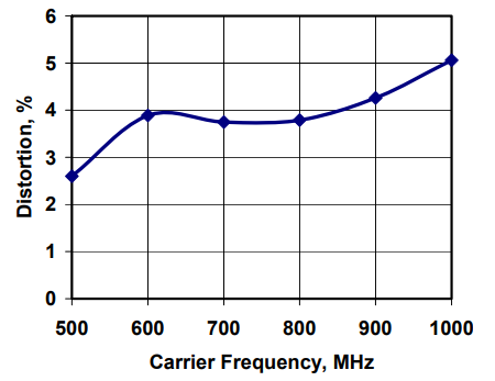
The LZY-2+ can be used to amplify an AM (Amplitude Modulated) carrier to a level of 5 watts (20 watts PEP) with typically less than 5% AM distortion when modulated at 90%. Measured AM distortion is shown in Figure 5.
FM Amplification
The LZY-2+ will typically produce a minimum of 32 watts CW or higher, and is limited only by the overdrive threshold limits set for the input signal as described in paragraph 4.1.
Linear Pulse Amplification
The LZY-2+ is ideal for linear pulse or pulse train amplification to faithfully reproduce a pulse signature to the 20 to 30 watt peak power level. The pulse width and duty cycle are not limited at these power levels because of the Class A amplifier operation.
Broardband 500MHz TO 1000MHz Swept Signal
For swept linear applications at 20 watts, the LZY-2+ will accept a constant input and produce an output level within +1.5dB (+0.5dB typical).
Feedforward Amplification
The LZY-2+ can be used as a main amplifier or error amplifier in a cellular band or special mobile radio band feedforward application due to its low intermodulation distortion (IMD) and relatively flat phase, delay and amplitude characteristics.
Multi-Carrier Amplification (Cellular Band 869 to 894 MHz)
The LZY-2+ RF Linear Amplifier is directly applicable as a candidate for a Main Amplifier in a low power cellular amplifier FEEDFORWARD system or a Pre-Driver or Error Amplifier in a high power FEEDFORWARD system.
Additional uses are as forward and reverse power amplifiers in bi-directional amplifying system installations.
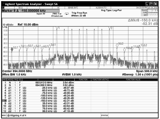
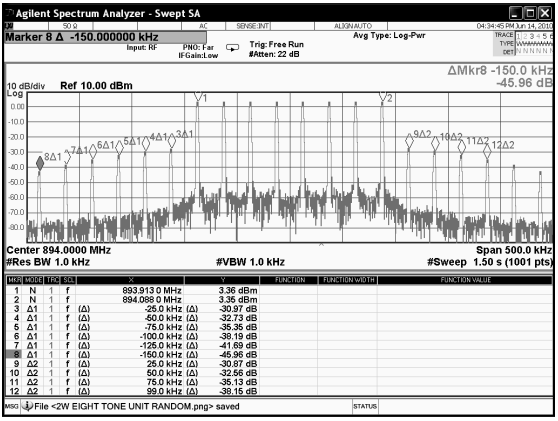
Figures 6a (random phase) and 6b (synchronous) illustrate the IMD products of the LZY2+ at 2 watts of total average RF output power for multi-tone operation with 8 carriers (0.25 watt or 24dBm each carrier). Peak envelope power (PEP) is 0.25 watt x 82 = 16 watts or 42dBm. Carrier spacing is 25kHz. Highest adjacent-channel spurious amplitudes are -43dBc for random phase and -31dBc for synchronous. The data were taken using the 8-tone Aeroflex-RDL Intermodulation Distortion Simulator "IMD-801D-03A". The low reference levels on the spectrum analyzer displays are due to the use of external attenuators in the test instrumentation.
Figure 3a (on Page 8) illustrates the IMD products at 4 watts of total average power, with two carriers (2 watts or 33dBm each). PEP is 2 watts x 22 = 8 watts or 39dBm.
Figure 3b similarly illustrates the IMD products at 10 watts of total average power, with two carriers (5 watts or 37dBm each). PEP is 5 watts x 22 = 20 watts or 43dBm.
As a Pre-Driver to loop 1 in a feedforward system, the IMD level should be -70 dBc. When used as a Main Amplifier, the IMD should be in the -32dBc range, and as an Error Amplifier, in the -40dBc to -50dBc range. All of these criteria are met by the LZY-2+ at various average power levels as illustrated by Figures 6a and 6b.
These data and performance pertain to the 869 MHz to 894 MHz cellular band but could also apply to the SMR band (Special Mobile Radio) between 935 to 940 MHz and any segment of the 500 to 1000 MHz range in which a feedforward system is of interest.
Alternative Heat Sinking / Cooling
The LZY-2+ RF Linear Amplifier electrical specifications in Table 1 are guaranteed when the RF Linear Amplifier module is operated on the factory supplied heat sink, and the cooling fan is running without restricting air flow.
Physical limitations of certain equipment configurations may require the user to provide alternative methods of heat sinking / cooling.
In these cases, the user can remove the RF Linear Amplifier module from the factory supplied heat sink by disconnecting the wires between the cooling fan and the module then removing the four mounting screws holding the module to the heat sink.
The user must then provide an alternative heat sinking /heat removal method that provides an equivalent thermal resistance of 0.08°C/watt to realize the unit electrical performance specified in Table 1. (See Paragraph 4.2 for thermal considerations)
Depending on the approach to cooling, alternative methods may increase or decrease the thermal resistance of that interface resulting in operation of the amplifier at a lower or higher temperature rise above ambient.
A qualified engineer or technician should be responsible for designing and evaluating the alternative heat sinking method.
Failure to provide the proper heat sinking will result in module overheating which in turn will activate the automatic thermal shutdown circuit when the module temperature exceeds +65°C.
Quality Assurance Provisions
Acceptance Test Procedure
All LZY-2+ amplifier assemblies are subjected to 100% factory RF testing in accordance with a written Acceptance Test Procedure in which RF performance parameters and electrical features are tested and verified. Certificates of compliance are available.
RF performance data is recorded and inspected for conformance within the limits set forth in Table 1.
Currently, each unit is subjected to a DC burn-in test for 72 hours with the input and output ports terminated in 50 ohms. This is a worst case condition for the amplifier since, when terminated, the DC power dissipated in the amplifier circuitry exceeds the amount dissipated when Class A RF power is being generated.
Performance is compared before and after the DC burn-in. 100% DC burn-in testing will continue at our discretion until sufficient history is generated to reduce or eliminate this test.
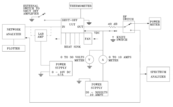
Acceptance Test Setup
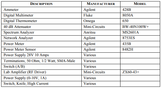
Figure 7 illustrates the test position setup used to perform acceptance testing on the LZY-2+ for the majority of the performance parameters specified in Table 1.
Test Equipment
The test equipment required to perform the acceptance tests is detailed in Table 2. In the event any item of test equipment is unavailable, equivalent equipment may be substituted. All test equipment should be turned on 30 minutes prior to start of test.