MAR/RAM Kit Test Board Instructions for Use
(for testing all MAR-SM AND RAM models)
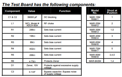
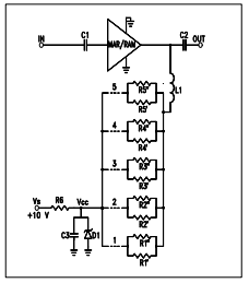
MAR-SM and RAM Models are series of amplifiers. They have different device voltages and currents (refer to catalog spec). The test board has been constructed in such a way as to make it useful for evaluating all the devices by suitable selection of bias resistor. This is done by soldering jumper wires across the dashed-lines positions 1 to 5 shown in Fig.1. The positions are defined in the table.
Procedure
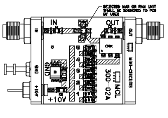
Follow these steps to use the Test Board. Figure 2 shows the layout.
- Solder selected MAR-SM or RAM unit onto Test Board.
- Make DC connection by soldering jumper wire in accordance with the table, depending on the selected MARSM or RAM model. All other positions should be open.
- Calibrate test setup.
- First, connect the RF output port of the test board to Network/Spectrum analyzer. Then, apply +10 V DC (10.2 V max). Finally, apply RF input to the test board from Network Analyzer.
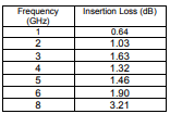
- Test Board has Insertion Loss due to the length of its lines, DC blocking capacitors and RF choke as shown below. Add this loss to the measured gain to get actual gain.