Using the Catalog Specifications to Determine MMIC Reliability
Specification pages for MMIC (Microwave Monolithic Integrated Circuit) amplifiers in the Mini-Circuits catalog contain graphs of typical MTTF (Mean-Time-To-Failure) as a function of Junction Temperature. To use one of these graphs it is necessary to know the junction temperature of the particular device. This Application Note provides guidance for determining the junction temperature.
Junction temperature TJ is given by the formula:
Where:
V is the DC voltage at the bias terminal of the device. For voltage-operated models such as the MNA series it is simply the supply voltage. For current-operated models such as ERA it is the voltage generated by the device when bias current is applied to it; if actual measurement is not practical, use the "Typ."value of device voltage in the catalog.
I is the DC current. For voltage-operated models it is the current flowing into the device when the specified supply voltage is applied. As alternative to measuring it, use the "Typ."DC operating current in the catalog. For current-operated models it is the bias current applied to the device, determined by the external power supply and biasing components.
θJC is the thermal resistance internal to the device, from its hottest semiconductor junction (or channel, in the case of a FET amplifier) to the case of the device (see below for definition). Its units are: degrees C per watt of power dissipated.
The actual power dissipated in a Class A amplifier is somewhat less than the product of V and I, because a portion of the DC power is converted to RF output that goes to an external load. The formula above takes the conservative approach of neglecting this effect.
TC is the case temperature of the device in degrees C, defined as the temperature of the mounting surface of the leads unless the specification page states otherwise. It is best to measure it with a thermocouple under actual conditions of operation. If this is not practical, a useful result for a device surface-mount soldered on a PC board can be obtained by adding an average value of temperature rise above the ambient air that exists in the vicinity of the PC board. For a device dissipating up to 0.2 watt, a 6-degree ambientto-case rise can be assumed. For a device dissipating more than 0.2 watt, assume 11- degree rise. Example: For ERA-33SM, power dissipation = 4.3V X 0.04A = 0.17W. Since this is less than 0.2W, assume 6-degree ambient-to-case rise.
The graphs give MTTF in years. To convert to hours, multiply by 8760 (24 X 365). Another common measure of reliability is FIT (Failures-In-Time), sometimes called FITs or FIT rate. It is failures per billion (109 ) hours. To convert MTTF (hours) to FIT, invert the MTTF number and multiply the result by 109 .
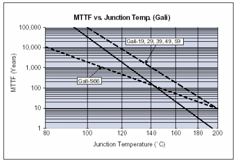
To illustrate, the graph for the Gali series of amplifiers in the Monolithic Amplifiers section of the Mini-Circuits catalog is reproduced below. The two dash line curves apply to the respective Gali models identified on the graph. The solid curve applies to all of the other Gali models listed in the catalog pages. As an example, consider Gali-59 operating in a 70°C ambient environment. The catalog gives the following.
- Current = 65mA
- Typ. Device Volt. = 4.8V*
- Thermal Resistance = 209°C/W
Since the device dissipation (4.8V X .065A = 0.312W) is greater that 0.2W, temperature rise in the user's PC board is taken to be 11°C per the rule given above. Typical junction temperature is therefore 4.8 x .065 X 209 + 70 + 11 = 146°C. Reading the graph, MTTF = 600 years, or 5.3 X 10⁶ hours, which is equivalent to 190 FIT.
*This room-temperature value is conservative. At 70°C device voltage is less, so the dissipated power and junction temperature would be less and MTTF would be greater. For a detailed discussion of temperature effects refer to the application note on biasing MMIC amplifiers, AN-60-010.
