Enhanced Linearity in the HELA-10 Power Amplifier
1.0 Introduction
To better satisfy the high linearity requirements of multiple-carrier wideband communication systems such as CATV when using Mini-Circuits model HELA-10, a combination of techniques has been found advantageous:
- Biasing at a higher DC current for better second- and third-order intermodulation suppression.
- Improving symmetry in the application circuit for better second-harmonic cancellation and further second-order intermodulation suppression.
Application note AN-60-009 included a description of how 2nd order and 3rd order intermodulation intercepts (IP2 and IP3) are improved by operating at higher current in a 50-ohm system, and explained how the balanced amplifier configuration suppresses even-order harmonics and even-order intermodulation products. This new application note extends the work of AN-60-009 by showing how intermodulation performance is improved using specially designed transformers optimized for symmetry, both at normal current and at the higher current. It presents typical performance in a 75-ohm system as used in the CATV industry.
2.0 Application Circuit
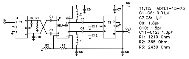
A schematic diagram of the application circuit used to obtain the results reported herein is given in Figure 1. It is designed for use in a 75-ohm system. The components are surface-mount. Bias resistors R2 and R3, which increase the DC current typically from 380mA to 520mA with 12V supply, are the same values as used in Section 4.2 of AN-60-009 for that purpose.
3.0 Tests Performed
Linearity testing was done with 2 tones 1MHz apart, swept over the frequency range 250 to 350MHz. Second- and third-order intermodulation products as well as second-harmonic power were measured. The significant 2nd order intermodulation product is the sum frequency 500 to 700MHz which, together with the 2nd harmonic, falls within the 50 – 850MHz CATV band. The output power at each tone was 14.5dBm.
In addition, the following characteristics were measured over the ranges 10 – 50MHz, 50 – 850MHz, and 850 – 1400MHz: Gain, Isolation, Input and Output VSWR, and Output Power at 0.5dB and 1.0dB compression.
All of these tests were done with 12V supply, utilizing the circuit in Figure 1 and 75-ohm instrumentation.
4.0 Results
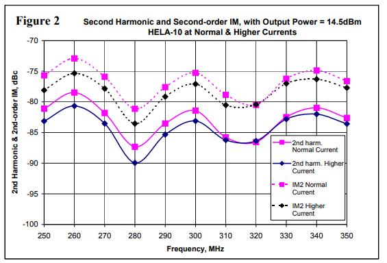
Figure 2 shows the typical power in each second harmonic as well as the typical power in the sum-frequency 2nd intermodulation product, relative to the power in each output tone. Up to 2.5dB advantage is obtained using the higher current. Note also that there is a 6dB difference between the 2nd harmonic and the 2nd order IM product. This is explained by the following analysis.
Consider a signal VIN consisting of 2 equal-amplitude cosine waves cos ω1t and cos ω2t that is inputted to a device having a nonlinear response:
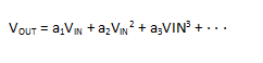
Ignoring 4th order and higher terms, the response is:

Expanding the squared term:

Note that the second-harmonic terms (for frequencies 2ω1 and 2ω1) inside the brackets of this equation have coefficient 1/2, while the second-order intermodulation terms (for the sum and difference frequencies ω1 + ω2 and ω1 – ω2) have coefficient 1. This shows that each of the second-order intermodulation products (IM2) is 6dB greater than each second-harmonic component in the output spectrum.
When the two test tones have frequencies close together, 300 and 301MHz for example (representing adjacent channels in a multi-carrier signal), the output spectrum in the second-harmonic region will contain the sum frequency 601MHz surrounded by the two second-harmonic components 600 and 602MHz, which are each 6dB below the 601 MHz component.
Figure 3 shows second-order intermodulation intercept, IP2, calculated from the intermodulation data.
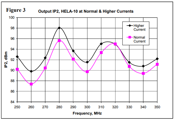
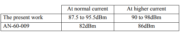
Table 2 compares the above IP2 results with AN-60-009 (the normal current in Figure 18 and the higher current in Figure 43, of AN-60-009). The present work shows typically 4 to 13dB better performance.
The advantage of up to 2.5 dB afforded by the higher current is on top of the advantage gained by the more symmetrical application circuit.
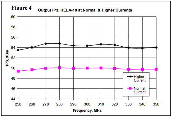
Typical third-order intercept is shown in Figure 4. Operating at the higher current yields 4dB better performance.
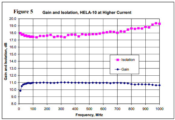
Gain and reverse isolation are shown Figure 5. Gain is essentially flat from 50 to 1000MHz. Directivity, which is the dB-difference between isolation and gain, is typically 7dB.
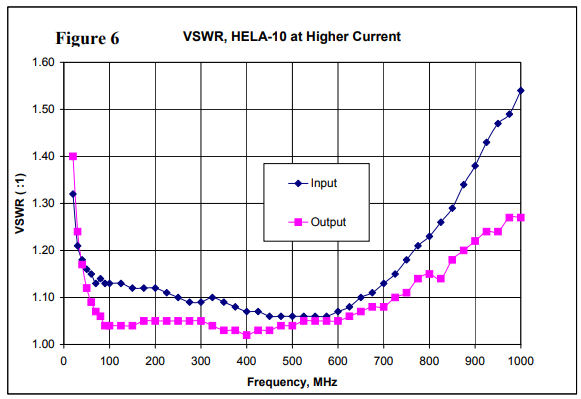
HELA-10 in its high-symmetry application circuit ensures excellent match to 75 ohms, as shown in Figure 6. Mid-band VSWR is typically 1.05:1. Over the range 50 – 850MHz it rises typically to 1.3:1 at the input and 1.2:1 at the output.
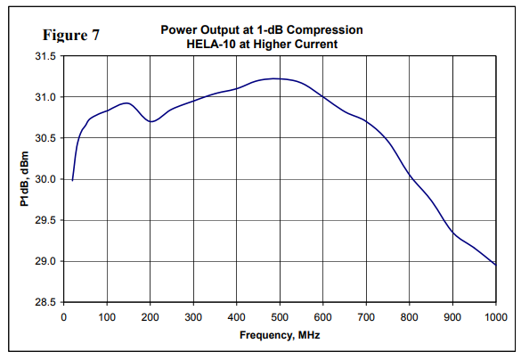
To complete the picture, power output at 1-dB compression is shown in Figure 7. In mid-band typical P1dB is 31dBm, and over 50 – 850MHz it remains above 29.5dBm.
5.0 Conclusion
Substantially improved performance has been demonstrated using an application circuit having enhanced symmetry that provides superior cancellation of second-order distortion. This is in addition to improvement in both second-order and third-order distortion performance achieved by biasing at a higher operating current.