MMIC Test Boards: Instructions for Use
Introduction
Mini Circuits manufacture a wide range of 4-pin MMIC surface-mount and drop-in amplifiers. Family of test boards, for evaluating these devices, has been designed as to make them easy to use by customer.
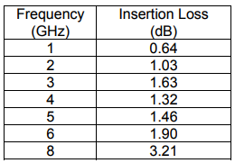
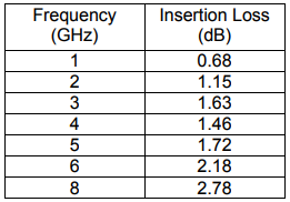
On the board, all components external to the amplifier, such as bias resistors, DC blocking and bypass capacitors, RF choke, together with the amplifier have been placed and soldered onto the Test Board. In this board, measured performance of the device under test is affected by these external components. Tables in 3 shows the loss of test board. Add the values given in 3 for respective models to the measured gain to get actual amplifier gain.
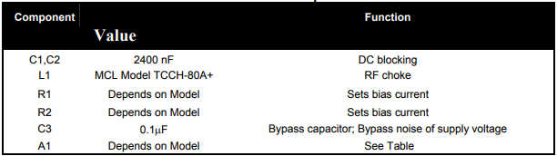
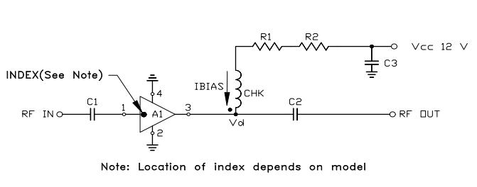
General Schematics
MMIC amplifiers have different device voltages and operating currents. This test board has been configured to use a fixed supply voltage, 12V, irrespective of the amplifier. DC current flowing through the amplifier is set by suitable selection of bias resistors.
Procedure for using Test Board
Follow these steps to use the Test Board.
- Calibrate the Network Analyzer.
- First, connect the RF output port of the Test Board to the Network Analyzer.
- Then, apply +12 V DC.
- Finally, connect the RF input port of the Test Board to the Network Analyzer and apply RF input. Gain is now displayed on the Network Analyzer.
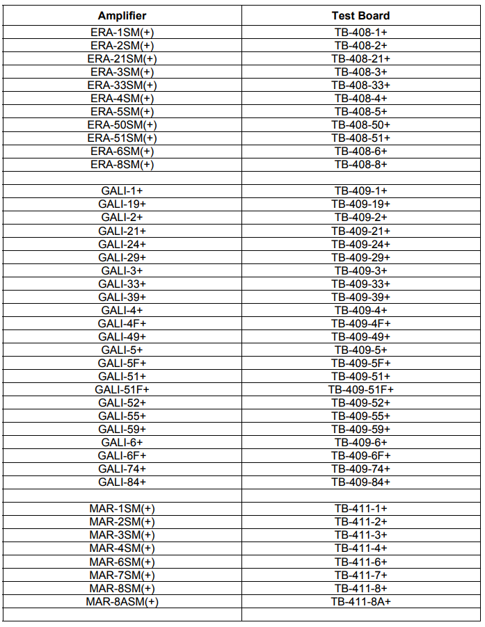
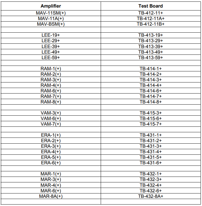
Test Board Loss

Amplifier and Test Board Cross Reference