High-Dynamic-Range MMIC Amplifier Supports CATV Upstream and Downstream Applications
Introduction
CATV systems typically require 75 Ω components with an operating frequency range of 40 to 1250 MHz in the downstream path and 5 to 200 MHz in the upstream path. Mini-Circuits' PGA-122-75+ 75Ω MMIC amplifier is designed and characterized for CATV applications with a frequency range of 40 to 1500 MHz, making it suitable for use in the downstream path. Within this range, the amplifier provides high dynamic range with typical output IP3 of +43 dBm, low noise figure of 2.9 dB and flat gain of 15.5 ± 0.1 dB. However, its specified performance is characterized in an application circuit matched for the downstream bandwidth (40 to 1250 MHz), which does not support use at lower frequencies. To extend its usability for upstream applications, Mini-Circuits has developed an application circuit to realize comparable amplifier performance over the 5 to 200 MHz band.
This article will present an application circuit for PGA-122-75+ over the 5 to 200 MHz band, enabling the amplifier to be used in CATV upstream applications. Test results will be provided to validate the amplifier's performance in the upstream application circuit.
Downstream Application Application Circuit (40-1500 MHz)
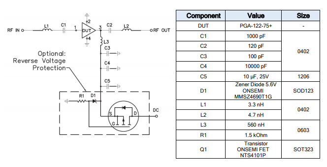
The recommended application circuit for PGA-122- 75+ from the model data sheet is shown in figure 1 includes DC blocking and matching circuitry at both the input and output. A biasing inductor (L3) and bypass capacitors (C3, C4, C5) prevent high frequency leakage from interfering with the power supply.
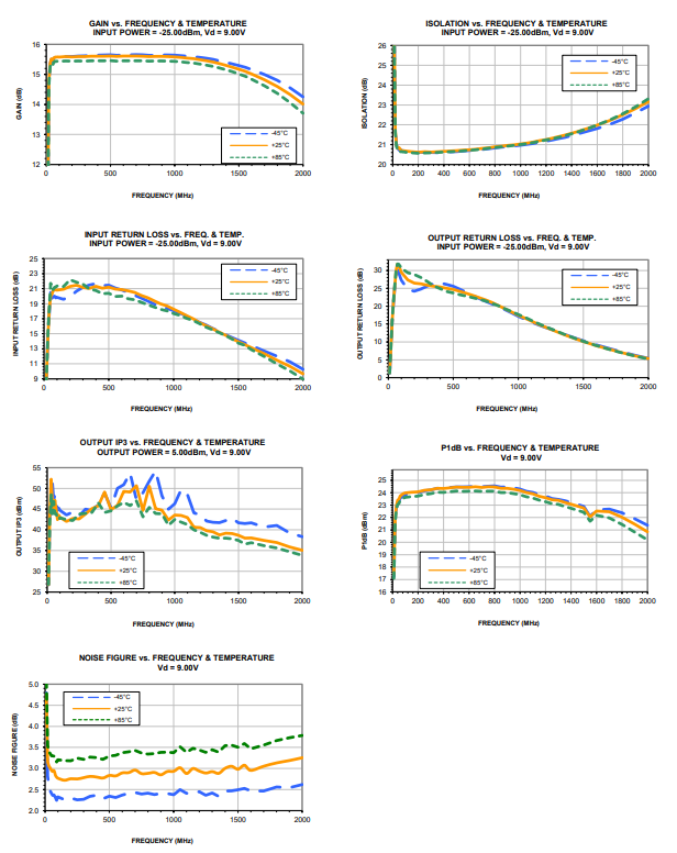
The amplifier was characterized in this application circuit for gain, isolation, input and output return loss, OIP3, P1dB and Noise figure following Mini-Circuits standard test procedures. Data plots of the measured performance are shown in figure 2 below for reference.
The amplifier exhibits excellent performance across its specified operating bandwidth from 5 to 1500 MHz, but performance degrades below 40 GHz as expected.
Upstream Application Circuit (5-200 MHz)
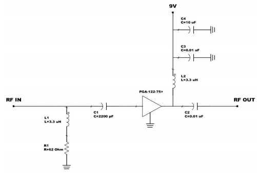
To extend the performance of the amplifier down to the upstream bandwidth, Mini-Circuits developed the application circuit in figure 3.
The matching circuitry at the input and output are modified to achieve better matching in the lower frequency range. The RF choke at the output also must be have a significantly higher value to prevent degradation of gain and output power.
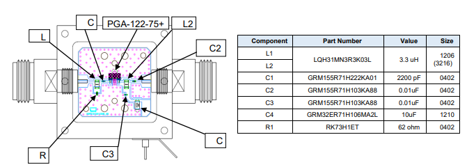
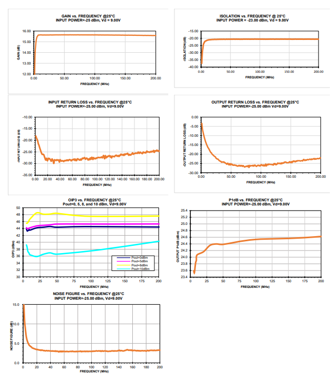
The test board in figure 4 was assembled to test the performance of PGA-122-75+ in the application circuit for the upstream bandwidth. Gain, isolation, input and output return loss, OIP3, P1dB and Noise Figure were swept from 5 to 200 MHz. The test data is plotted in figure 5.
The results of this test indicate that the amplifier exhibits comparable performance to the model spec down to 5 MHz in the new application circuit. This enables the amplifier to be used in upstream applications without sacrificing performance.
Conclusion
The application circuit for PGA-122-75+ presented in this article enables designers to use PGA-122-75+ 75Ω MMIC amplifier for upstream CATV applications. This capability allows the same amplifier to be used in both the downstream and upstream paths, reducing system part counts and reducing costly qualification effort on the customer end.
Test boards for both downstream and upstream application circuits are available from stock to support customers evaluating the PGA122-75+ for their systems.
