Fixed attenuators help minimize impedance mismatches
Proper application of fixed attenuators can help reduce impedance mismatches in high-frequency circuits and systems.
Fixed attenuators are invaluable problem solvers for circuit-level and system-level designers. In addition to controlling amplitude levels, fixed attenuators can improve the impedance match between impedance-sensitive devices, such as amplifiers and filters, and provide the isolation needed to stabilize oscillators.
Unfortunately, not all RF components and transmission lines are created equal. Although most components are nominally specified at 50 ohms (and, in the case of cable-television or CATV systems, 75 ohms), their impedances are comprised of complex reactive elements which can add and subtract under different phase conditions. Under ideal conditions, when a load is perfectly matched to a source, maximum power available from that source is transferred to the load. Under these ideal conditions, there are no reflections, and the reflection coefficient is zero. But when the operating conditions are less than ideal (as in all real-world applications), not all of the source power is absorbed by the load; the remaining power is reflected back to the source. When the load is an open or short circuit, all of the power is reflected back to the source, and the reflected voltage is the same as the forward voltage, resulting in a reflection coefficient of unity. In simple terms, when the load impedance of a device differs from the characteristic impedance of a system or other device, the voltage between the two units will fluctuate.
The reflection coefficient can be expressed in terms of the load impedance and the characteristic impedance as:
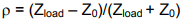
The ratio of the peak voltage to the minimum voltage, which is known as the voltage standing wave ratio (VSWR), can be expressed in terms of the load and characteristic impedances as:

The VSWR is a figure of merit for impedance match (or mismatch). In an attenuator, it is a measure of the deviation from 50 or 75 ohms of the component's input and output impedances. A perfect match is represented by a VSWR of 1.0:1, while a worse-case mismatch is represented by an infinite VSWR of 8 : 1. A VSWR that is slightly higher than 1.0:1 represents a slight mismatch from the ideal match, and is generally the goal sought by adding attenuators to a multiple component design or test system.
A fixed attenuator can help to lower the VSWR of cascaded (connected) components by providing isolation between the impedances, effectively masking the impedance mismatches. It is important to note that in a receiver, an attenuator will also play a part in the system noise figure, since the unit's attenuation value can also be thought of as its noise figure. For example, a 3-dB fixed attenuator that is inserted prior to a low-noise amplifier (LNA) in a receiver front end will effectively set the noise figure of the receiver to a minimum of 3 dB. The cascaded effects of the noise figures and losses of the components following the attenuator, including the LNA, will increase the noise figure considerably beyond 3 dB, however.
Similarly, the use of attenuators in a test system with a spectrum analyzer, for example, will affect the test-system dynamic range. Since the dynamic range is essentially the difference between the highest-level signal and the minimum discernible signal, the dynamic range will decrease by an amount equal to the total attenuation added.
In test setups, even minimal-valued attenuators, such as 1-dB units, can aid in minimizing mismatch errors. The choice of attenuator depends on the sensitivity of the measurement equipment, the type of device under test (DUT), and the maximum allowable signal level to the test equipment. If an active device, such as an amplifier, is under test, with a rated output level of +27 dBm, but the maximum input rating of the spectrum analyzer is +25 dBm, an attenuator with rating of 5 dB or more will provide adequate protection for the analyzer while also serving to minimize mismatch uncertainty. Of course, based on the attenuation flatness of the device, it may be possible to specify a lower-valued attenuator, provided that its variations in attenuation (attenuation flatness) are within acceptable limits. In this case, a 4- dB attenuator with better than ±1 dB attenuation flatness (which means that its attenuation ranged from 3 to 5 dB) would still provide adequate protection for the spectrum analyzer's input mixer.
Several line of drop-in and coaxial fixed attenuators are available from Mini-Circuits at attenuation values from 1 to 40 dB and for frequencies from DC to 18 GHz. These attenuators are available for both 50- and 75-ohm system, with attenuation flatness ranging from ±0.2 dB for lower-valued attenuators to a still modest ±0.6 dB for 40-dB attenuators. Minimum and maximum VSWRs are given for all units to help anticipate the effects of a particular attenuator (beyond the basic signal attenuation) on a communications or test system.
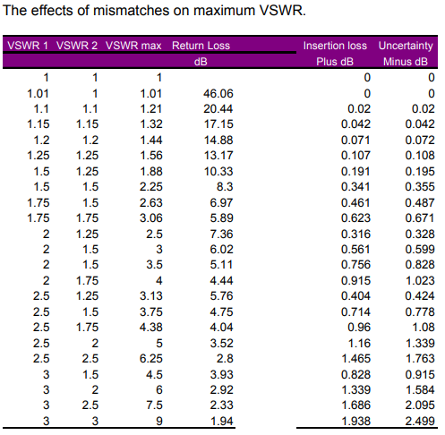
When attempting to determine the total VSWR created by the connection of two components, it is generally safe to assume that two VSWRs will tend to multiply rather than add. For example, when connecting a component with a VSWR of 3.0:1 to a second component with a VSWR of 1.50:1, the resulting maximum VSWR will be 4.50:1, with a corresponding return loss of 3.93 dB. Because of this, the effects of mismatch can be minimized by selecting an attenuator with the lowest possible VSWR. The table shows the effects of combining two components in terms of their maximum VSWR and return loss. The ideal condition, where both VSWRs are 1.0:1 and there are no reflections, results in infinite return loss. But as the VSWR for each component increases, the maximum VSWR increases as the product of the two individual VSWRs.
The table was created with a handy Windows-based program called VSWR Calculator, detailed by author Steve Hageman of Agilent Technologies (Santa Rosa, CA) in his article, "Program predicts VSWR-mismatch RF uncertainties," appearing in the February 1, 2001 issue of EDN. The program can be downloaded for free from the site at www.sonic.net/~shageman/vswr.html.