DAT Series Powered through a Voltage Divider Network
Background:
The Mini-Circuits DAT series is specified to operate with supply voltages over the range of 2.7V to 3.3V. When operating over this range, the parts meet all their specified performance parameters over the operating environmental ranges. However, under lower than specified voltage conditions, performance is not guaranteed. Furthermore, as with any silicon driver, there is a risk of the device entering into a latch-up condition and then becoming non responsive to commands and having to be powered down and repowered under proper voltage to recover.
In many systems, 3V may not be available on the PCB. In these cases, the designer must generate the 3V from a higher level voltage supply. A clean method of generating the 3V is to use a voltage regulator IC; these devices have the capability to supply constant voltage to the DAT and other circuits, as long as the load does not exceed the maximum current capacity of the regulator chip.
Another approach is to simply divide the voltage using a simple Resistive Voltage Divider (RVD) to step down a higher level voltage to the desired 3 Volts.
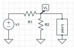
In the case of a voltage divider circuit the voltage to the load can be expressed as follows:
If we neglect the current consumption of the load, the voltage on the load is:
During steady state operation the DAT units consume approximately 100 μA; however, during startup and transition from one attenuator state to another, the DAT draws higher current for a short period of time. Although this "surge current" is relatively low, when using a Voltage Divider Circuit to drive Vdd, caution is required to ensure that the induced voltage drop does not risk proper operation.
Evaluating the effect of Surge Current
To validate the effect of surge current on the DAT series performance, tests were designed to:
- determine the range of surge current levels
- assess the impact of these levels on the DAT
- develop a recommended voltage divider circuit to drive the part from +5V
Pre Screening
To assess the limits of the surge currents, hundreds of units were tested for surge currents on startup and during transition. From this testing, a smaller sample was selected to assess expected maximum surge currents.
Test setup
Tests to measure the surge current were performed in accordance with Figure 2.
A 1kO resistor was placed in series to the RVD and Vdd pin of the DAT whereby the voltage drop across this resistor is directly proportional to the current supplying the DAT. Figure 3 shows the typical oscilloscope traces on both sides of the resistor as well as the differential voltage which is proportional to the current. From this plot the magnitude and duration of the surge current it is evident.
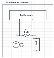
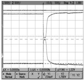
- Top curve: the voltage measure before the resistor
- Middle curve: the voltage measured after the resistor
- Bottom curve: the voltage drop on the resistor, which correlated to the current flowing through the DAT
Validating Latchup Limits
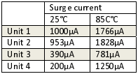
Hundreds of units were tested to establish the expected range of surge current at both 25°C and 85°C.
- Units show surge current up to 1mA at 25°C and up to 1.8mA at 85°C
- The duration of the surge is up to 0.2μs
- Surge current duration is dependent on the rise time of the power supply voltage
Given the range of surge current up to 2mA, a considerable drop in voltage across a voltage divider network could occur and potentially pose a risk of latchup. To assess this, the DAT was tested with units that exhibited high surge currents.
These units were tested in a typical application circuit, fed from a voltage divider as part of this validation effort and showed latchup when the selected voltage divider resistors allowed the voltage drop to bring Vdd below 2.4V.
Conclusion
The Vdd supply circuit must be able to supply a surge current during startup and during switching transitions. Surges were measured up to 1.8mA. For safe margin, designers should configure their circuits to support up to 2mA of surge current. This means that the series resistor (R1 in Figure 1) in the RVD pair need to be small enough that the IR Drop (2mA x R) is NOT sufficient to allow the Vdd to drop below 2.7 volts
For a 5.5VDC power supply, a voltage divider of 499Ω and 680Ω will be able to provide the required surge current without latching up.
