Advantages of Cascading Reflectionless Filters
INTRODUCTION
Cascading filters in series is commonly used to enhance stopband rejection and steepness in the transition band. The technique can also be used to combine high pass and low pass filters to create a band pass response. While using filters in series does achieve these desired effects, conventional filters are fully reflective in the stopband, and the reflected signal creates standing waves in the signal path between filter stages. This can introduce problems in the passband such as ripple and phase instability, which distort the desired signal and degrade system performance.
Mini-Circuits X-series reflectionless filters employ a novel filter topology in which stopband signals are internally terminated rather than reflected back to the source. This feature affords RF and microwave system designers many advantages over conventional filters. One such advantage is the ability to cascade filters in multiple sections and eliminate undesirable effects that often arise when conventional filters are cascaded. This article will demonstrate how reflectionless filters eliminate these problems when cascaded, allowing greater design flexibility and improvement in system performance.
SIMULATION
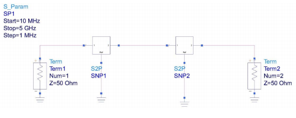
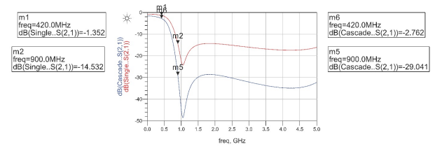
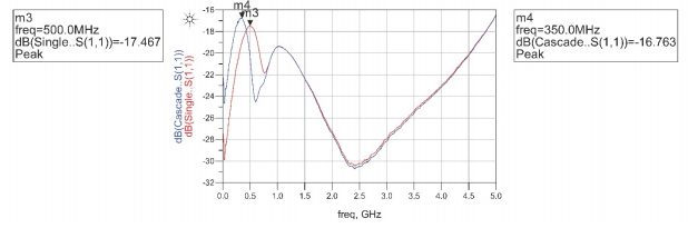
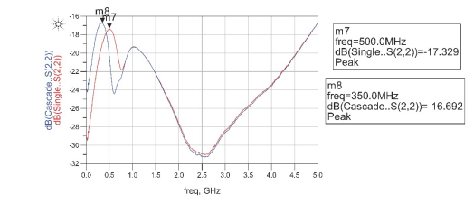
Reflectionless filter model XLF-421+ will be used as an example for demonstration. XLF-421+ is a reflectionless low pass filter with a passband from DC to 420 MHz. It achieves 1.4 dB passband insertion loss, 14 dB stop band rejection from 900 to 5200 and 24 dB stop band rejection from 5200 to 18000 MHz. A simulation of the S-parameters when two XLF-421+ filters are cascaded is shown in figure 1. Simulated data for insertion loss (figure 2) shows the expected enhancement in stopband rejection as well as steeper roll off in the transition when two filters are cascaded. Meanwhile the effect on input and output return loss (Figures 3 and 4) is minimal. Note that the simulation data exhibits no ripples, distortion or other unwanted behaviors for two reflectionless filters in cascade that might otherwise appear if reflections or phase instability were present in the system.
TEST RESULTS
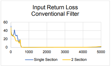
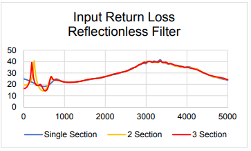
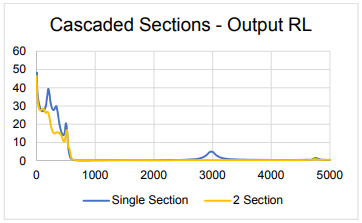
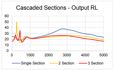
To further validate the advantages of reflectionless filters in cascaded configuration, testing was performed to compare reflectionless filter XLF-421+ to conventional filter NLP-550+ when cascaded. The units were soldered on test boards and the test boards were interconnected in series and connected to a vector network analyzer. The reflectionless filter was tested in 1, 2 and 3 sections, and the conventional filter was tested in 1 and 2 sections. Insertion loss, input and output return loss, and group delay were swept from DC to 5000 MHz for each structure. The measurement data is presented in figures 5a through 5j.
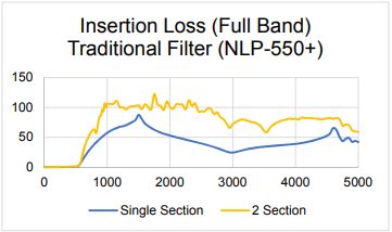
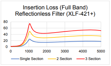
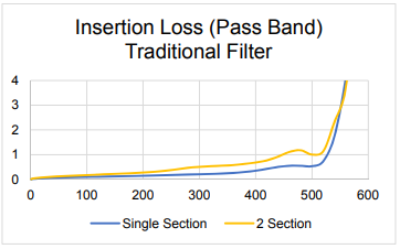
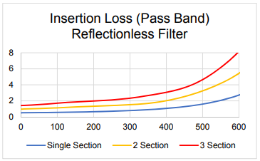
The insertion loss curves for the conventional filter exhibit an expected increase in stopband rejection when two filters are cascaded in series. However, obvious ripple appears across the stopband in the two-section curve. This is due to the unstable phase relationship between the through-signal and reflected signal. Additionally, unwanted ripple is present in the passband close to the band edge of the two-section curve. This is a result of return loss degradation in the passband and reflections in the transition. By contrast, the insertion loss performance for the reflectionless filter repeats itself nicely when cascaded in 2 and 3 sections without any of the ripples or distortion seen in the case of the conventional filter.
Figures 5e through 5h show the effect on return loss when the two types of filters are cascaded in multiple sections. The conventional filter exhibits significant degradation in input and output return loss in the passband when cascaded in two sections - by as much as nearly 20 dB in some regions. When the reflectionless filter is cascaded in two sections, on the other hand, input and output return loss varies over the passband, but the same degradation is not evident, and return loss actually increases at some frequencies relative to that of a single filter. This illustrates that an improvement in return loss in the passband and the stopband can be realized by cascading reflectionless filters versus conventional filters.
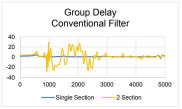
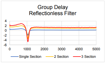
Lastly, group delay (figures 5i and 5j) for two cascaded conventional filters presents wild variations over frequency, which results in signal distortion in the passband. By comparison, group delay remains flat through the passband, transition, and stopband when the reflectionless filter is cascaded in 2 and 3 sections. This shows that reflectionless filters essentially eliminate distortion related to phase instability when cascaded in series.
CONCLUSION
One advantage of reflectionless filters is the capability to cascade filters in multiple sections while virtually eliminating the detrimental effects of signal reflections. This makes these filters extremely flexible building blocks for applications where greater stopband rejection or sharper roll-off are desired, allowing significant improvements in overall system performance.
