Using the RSW-2-25PA+ Switch
Model RSW-2-25PA+ is a single-pole 2-throw (SPDT) RF switch. The switched (output) ports are reflective with high impedance in the OFF state.
The following procedures are required to ensure reliable operation of RSW-2-25PA+:
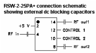
- External DC blocking capacitors are required on the RF In, RF Out 1, and RF Out 2 ports. The impedance of these capacitors should be less than 5 ohms over the operating frequency range. Figure 1 shows how they are to be connected by the user.
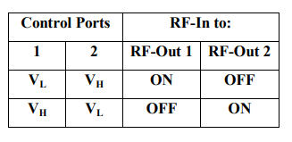
- RF performance is specified for the following voltages: DC Supply voltage VS (at Pin 2) is +5V. Control 1 and Control 2 voltages are 0 ±0.2V for Low state (VL) and +5 ±0.2V for High state (VH). The control logic is given in Table 1. While the specifications of the unit are derived under these conditions, it can operate properly with VS up to 7V and VH in the range (VS -0.2V) to 7V.
- The absolute maximum (no-damage) voltages are as follows. Supply voltage: +8V, Control voltage: -0.2V and +8V.
- As a precaution, RF power should not be applied to the RF In, RF Out 1, or RF Out 2 ports before specified DC Supply voltage and Control 1 and Control 2 voltages are applied to the device. This is to ensure that each path through the switch is fully ON or OFF, which is the condition for which the maximum RF input power applies. An intermediate voltage might result in higher than specified insertion loss, with resulting increase in power dissipated by the device.