Frequency Doublers: Introduction, definition of terms, Q&As
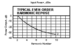
Mini-Circuits' frequency doublers offer a new degree of freedom in designing frequency multiplier chains. Their multi-octave band width and excellent rejection of fundamental and third harmonics enable a significant reduction in filter requirements. In addition, they operate with 50-ohm impedances at input and output ports and are not very sensitive ta input power. They perform well from 0 dBm to +20 dBm input. The frequency doubler may be operated as a quadruped. Referring to the figure, the fourth harmonic will be approximately 12 dB less than the second. When filtering and power level considerations are made, there may be situations where operating the doubler as a quadrupler is a practical alternative to two successive stages of doubling. Mini-Circuits' frequency doublers are economically priced while covering the very broad frequency range from 5 KHz to 3000 MHz. They offer a very low conversion loss, from 11 dB, and high spurious rejection 40 dB. These doublers give exceptional unit-to-unit matched performance.
Frequency doubler measurements
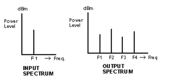
Frequency doublers generate the second harmonic of an input signal, while suppressing fundamental and odd harmonics. One test determines the conversion loss as the dB-difference between the fundamental input power and the second harmonic output power. Another test measures the output power of the "spurious" spectral components: the fundamental, and the third and fourth harmonics, each relative to the desired second harmonic output. The Figure below shows the setup for both tests. The amplifier and attenuators ahead of the D.U.T. are chosen to drive it at the specified fundamental input power, typically in the +5 to +15 dBm range, as well as to ensure a matched source impedance. Mini-Circuits amplifier model ZHL-2 is suitable for testing the lower-power D.U.T.'s, and ZHL-1000-3W or ZHL-5W-1 for the higher power ones. The filter can be lowpass or bandpass; its purpose is to present a harmonic free input signal to the D.U.T. For wideband testing, different filter cut-off frequencies have to be used according to the frequency being applied.
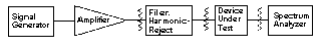
For the conversion loss test, replace the D.U.T. with a "through" connection, and obtain a 0 dB reference on the spectrum analyzer. Then reconnect the D.U.T. and measure the second harmonic with the analyzer. Calibrate the spectrum analyzer at the fundamental and second harmonic, to account for its flatness, using a power meter. For the spurious output test, obtain a 0 dB reference on the spectrum analyzer, tuned to the second harmonic, with the D.U.T. in place. Then tune to the fundamental, and third and fourth harmonics, and measure each on the analyzer relative to the 0 dB reference.
Modern Definition Of Terms
Frequency doubler
A non-linear device that efficiently produces an output that is twice the frequency of the signal applied to its input.
Conversion loss
Conversion loss is a measure of the difference in power level between input signal F1, and output signal F2 expressed in dB.
Harmonic outputs
F1 is input at frequency. F1
F2 is desired output frequency (2 X F1)
F3 is harmonic output (3 X F1)
F4 is harmonic output (4 X F1)
The MCL Handbook specifies harmonic power output F1 as a measure of the output power level at frequency F1 relative to the power at F2. Similarly, harmonic output F3 is a measure of the relative power level of frequency F3 to F2. And harmonic output F4 is a measure of the relative power level at F4 to F2.
RF input power level
The required RF power that must be applied to the input of the frequency doubler in order that the "doubling action" will be performed and is the power range for which conversion loss is specified. At low RF input levels, the conversion loss will increase beyond its specified maximum level. At high RF input levels, the frequency doubler can burn out.
Most Often Asked Questions About Frequency Doublers
Q. How does the return loss at the output of a frequency doubler vary as input power changes?
A. Return loss is influenced by how hard the diodes are driven in their conducting state. As input power to the frequency doubler is reduced, the impedance will increase. It is possible, as it increases, to notice an important in VSWR or return loss; as input power is further reduced, return loss will degrade. Thus return loss is a function of the input signal level fed to the frequency doubler.
Q. What is meant by the conversion loss of a frequency doubler?
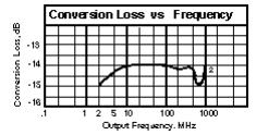
A. The conversion loss is the difference in power at the output of the frequency doubler (the second harmonic) compared to the power applied to the input (fundamental) in dB. The conversion loss will vary as a function of the power and frequency applied to the input of the doubler.
Q. What is the spectrum at the output of a frequency doubler?
A. Since the frequency doubler operates in a non-linear state, its output contains harmonics of the applied fundamental signal. The amount of odd-order harmonics is a function of the symmetry of the diodes when conducting at each half cycle of the input signal. Basically, all harmonics, including the fundamental, will appear at the output. Each even-order harmonic will appear approximately 12 dB lower than its previous even-order harmonic; for example, the 6th harmonic is about 12 dB lower than the 4th.
Q. Can I use a frequency doubler as a quadrupler?
A. Yes, by making use of the fourth harmonic rather than second at the output. There are two disadvantages to consider, however. First, the fourth harmonic output level is 12 dB lower than the second. Also, the harmonics closest to the fourth (the third and fifth) must be reduced, this could complicate filter requirements.
Q. Suppose I need a tripler. Can I somehow use a frequency doubler?
A. Use a different type of frequency multiplier, such as a comb generator or a Class-C amplifier.
Q. Will there be a change in the amount of harmonics generated by the frequence doubler as input power is varied?
A. No. The harmonics will remain the same but the power level associated with each harmonic will change as input level is varied.
Q. What happens to the output of a frequency doubler when it is driven too hard?
A. Think of a frequency doubler as a mixer with the same frequency signal applied to both the RF and IF ports; sum and difference frequency signals will appear at the output. When excessive signal level is applied, the frequency doubler will operate in heavy saturation, and higher-order harmonics will be greater in amplitude relative to the desired second-harmonic. In addition, the second harmonic output will not increase in linear proportion to the input so that effective conversion loss would be higher. Make sure the input power to the frequency doubler is within the power range specified for optimum performance.
Q. Can the input waveform be other than a sine wave?
A. Yes, a frequency doubler will operate with various input wave shapes. However, a square wave would probably provide higher efficiency since it would drive the device harder into its conducting and non-conducting state.
