Filters: Introduction, definition of terms, Q&As
In the operation of electronic systems and circuits, the basic function of a filter is to selectively pass, by frequency, desired signals and to suppress undesired signals. The amount of insertion loss and phase shift encountered by a signal passing through the filter is a function of the filter design. Similarly, the amount of rejection of an undesired signal is a function of the filter design.
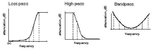
Mini-Circuits' filters are passive, they contain inductors and capacitors. Three types of filters, low-pass, high-pass, and band-pass are available. Two different low-pass filters have been designed to (1) provide high rejection of undesired signals very close to the pass-band and (2) to provide a linear phase versus frequency characteristic across the pass-band frequency range. A linear phase characteristic is essential when passing a pulse waveform in order to preserve the pulse shape and avoid a distorted waveform. High-pass filters have similarly been designed to provide high rejection of undesired signals very close to the pass-band. Constant impedance band-pass filters have been designed to allow signals to pass within the passband and to be rejected outside of this band. However, these filters provide a matched 50-ohm impedance both within and outside the passband. This is a very important characteristic especially when intermodulation distortion and non-linear devices, such as mixers and oscillators are to be considered. Refer to the article "Constant Impedance IF Bandpass Filters Improve Performance" for more details.
Mini-Circuits' filters are available in a variety of packages and connector styles. Pin plug-in and surface-mount packages are available to accommodate both commercial and military applications. In addition to the catalog models described on the specification sheets, Mini-Circuits designs and manufactures filters to specific customer requirements. Consult our Applications department for your specific needs.
The basic filter designs offered by Mini-Circuits utilizes a modified butterworth or "maximally flat" design, a modified Bessel-Thomson or flat delay design, and an Elliptic function design. All filters are specified by their amplitude response, both in the passband and reject-band, also by their VSWR and phase characteristic where applicable. For convenience, the 20 dB and 40 dB reject-bands are specified. The cut-off frequency, fco, of each filter is also given. This frequency corresponds to the 3 dB insertion loss point of the filter response. This frequency point easily allows the filter response to be normalized to fco.
The CAPD data given in the handbook for each filter has a significant amount of data points to clearly describe the filter performance characteristic. The data curves show the overall filter performance curves. Any resonances that would be available can easily be observed. The data and curves present a very accurate description of each filter and may be used in conjunction with various software programs designed to analyze system performance.
Modern Definition of Terms
Insertion loss
is equal to the difference in dB power measured at the filter input and at the filter output. The power measured at the filter input is equal to the measured power when the filter is replaced by a properly matched power meter or network analyzer. The input impedance of the measuring instrument should be equal to the characteristic impedance of the filter or system. Unless otherwise specified, Mini-Circuits' filters are designed for 50 ohm systems. Similarly, the power measured at the filter output is equal to the measured power when the filter is terminated by the same measuring instrument as discussed. The insertion loss will be equal to the sum of three loss factors. One is the loss due to the impedance mismatch at the filter input, the second is due to the mismatch at the filter output, and the third is due to the dissipative loss associated with each reactive element within the filter.
Passband
is equal to the frequency range for which the filter insertion loss is less than a specified value. For example, most of the Mini-Circuits' low-pass filter models are specified to have a maximum insertion loss value of 1 dB within the passband.
Stopband
is equal to the frequency range for which the filter insertion loss is greater than a specified value. For example, most of the Mini-Circuits' low-pass filter models are characterized by the frequency range where the insertion loss is greater than 20 dB and 40 dB in the stopband. These two values are arbitrary; they could easily have been chosen for some other values. The purpose of selecting 20 dB and 40 dB is two-fold. One is to provide the design engineer with a simple means to calculate the frequency selectivity of the filter. The second is to allow a quick calculation of the suitability of the filter in a particular situation. Since 20 dB or 40 dB represent sufficient loss requirements in many systems, these values were chosen. The data in this handbook provides actual loss values as a function of frequency. For many Mini-Circuit filters the stopband losses can exceed 60 dB.
Cut-off frequency, fco
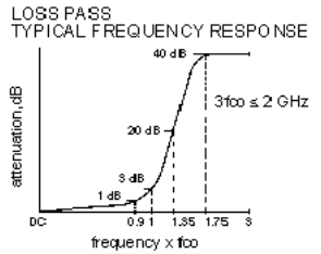
is the frequency at which the filter insertion loss is equal to 3 dB. It is a very convenient point for expressing the passband and stopband boundary points. In addition, it allows a convenient means to normalize the frequency response of a filter. For example, if the frequency of a low-pass filter response were divided by fco then the resulting response would be "normalized" to fco. A typical normalized low-pass response is shown in figure 2. The normalized response allows the design engineer to quickly specify the filter needed to meet his system requirements. For example, considering the low-pass filter, the upper frequency range of the passband is equal to 0.9 times the cut-off frequency. If the passband requirement is DC to 225 MHz then fco, equals 250 MHz. Similarly the stopband frequencies can be calculated.
VSWR
is a measure of the impedance looking into one port of the filter while the other filter port is terminated in its characteristic impedance, namely, 50 ohms. Many times, the impedance match is expressed in terms of return loss. The conversion between return loss and VSWR is easily attainable using the chart given in Section 0. Most of the filter models shown in this handbook are designed to present a good impedance match in the passband and a highly reflective impedance match in the stopband. Typically the VSWR in the center of the passband is better than 1.2 to 1 and the VSWR in the stopband is typically 18 to 1, very highly reflective. One very notable exception to this VSWR characteristic is the constant impedance band-pass filter series. In these models, both filter ports present a good impedance match in the passband and stopband. Return loss data over the entire frequency range is given in the CAPD pages.
Center frequency
is the frequency at which band-pass filters are geometrically centered. For example, if f1 and f2 represent the 3 dB frequency points of a band-pass filter, then the center frequency f0, is calculated as follows:
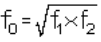
When the bandwidth, f2 - f1, is a small percentage of the value of f0, then f0, the geometric mean between f2 and f1, will approximately equal the arithmetic mean between f2 and f1.
Linear phase or flat time delay
Filters have the characteristic of enabling the signal at the filter output to have a constant phase difference for each fixed increment of frequency difference of the signal. Thus:

where K is a constant.
Mini-Circuits' PBLP filter models utilize a Bessel-Thomson design to achieve the linear phase characteristic or flat time delay. This enables the transmission of various frequency components contained in a pulse waveform to be delayed by the same amount while traveling through the filter thus preserving the pulse wave shape.
Group delay
is the amount of time it takes for a signal having a finite time duration, such as a pulse, to pass through the filter. Ideally, all frequencies present in the signal should have the same time delay, so that the signal will not be distorted. In most types of filters this is not the case, and group delay defined as dØ/df varies with frequency. For linear phase filters the group delay is constant. It is easy to compare the group delay between a linear phase PBLP low-pass filter and the high selectivity PLP low-pass filters given in the specifications. Referring to the data pages it is observed that the linear phase filters have a much lower and flatter value of group delay.
Most Often Asked Questions
Q. Is a filter a reciprocal device? Is it possible to interchange between input and output ports?
A. Yes. Filter response is unaffected as long as the source and load impedances are the specified value.
Q. I intend to use an MCL 50-ohm filter in a 75-ohm system. What might be the consequences?
A. The impedance mismatch will change the response. Pass-band ripple, stop-band rejection, and VSWR will be affected to a degree which depends upon the particular filter design.
Q. Does MCL offer surface-mount filters?
A. We offer surface-mount filters in this Handbook and are continually developing new filters to meet customer requirements. If your requirements are not met by the filters listed, please call our Applications Engineers.
Q. How does temperature influence filter performance?
A. Our filters are designed to operate from -55° to 100°C and meet our specifications over this full temperature range. There may be slight variations from room temperature performance.
Q. Can I cascade a low-pass filter with a high-pass filter to achieve band-pass performance'?
A. Yes, if their passbands overlap enough to avoid interaction of their skirt responses, which could increase the combined insertion loss. As a guide, select the two filters so that the resulting bandpass has at least 5 percent bandwidth at 1 dB insertion loss.
Q. How can I calculate a filter's rejection in the stopband?
A. Refer to the CAPD page in this handbook which shows data or a graph for a filter in the same series as the filter you need. If the cutoffs are not the same, scale all frequencies in the CAPD by the ratio of the cutoff frequency of your filter to the cutoff frequency of the filters whose data are listed.
Q. I have a 130 MHz crystal oscillator and I would like to reduce the harmonics at its output. Which 50 ohm filter series would you recommend?
A. In order to avoid frequency pulling of the oscillator and the generation of internal products, it is recommended that a matched broad band impedance be connected to the oscillator output. Although, Mini-Circuits' constant impedance filters would satisfy this criteria, they would not provide sufficient selectivity to substantially reduce the harmonics of the oscillator fundamental frequency output signal.
On the other hand, the low-pass filter series offered would provide excellent selectivity and would substantially reduce the harmonics of the fundamental. The problem, however, is that the filter impedance is highly reflective at the harmonic frequencies. This will cause the harmonic signals to be reflected back into the oscillator. The solution is to insert at least a 6 dB attenuator (12 dB return loss) between the oscillator and filter. The fixed attenuator section of this handbook offers a wide choice for your selection.
Q. I have a need to increase the selectivity performance of my system. I had chosen a PLP-100 low-pass filter. However, I now need 30 dB of attenuation at 146 MHz rather than the 20 dB specified. How should I proceed?
A. First determine your pass band requirements, that is, the maximum attenuation allowed within your band width required. Let us assume your maximum allowable passband insertion loss is 2 dB. Then referring to the data pages for low-pass filters, choose the filter model that provides 30 dB attenuation at 146 MHz and has the widest passband for an insertion loss of 2 dB or less. If the passband is too narrow for the filter chosen, then you can use and alternative selection process. Reconfigure your system to use two low-pass filters. The insertion loss in the passband of the combination will be additive. Therefore, two PLP-100 low-pass filters will provide less than 2 dB of attenuation and can provide 40 dB of insertion loss at 146 MHz. If less passband insertion loss is desired, then the second low-pass filter can be chosen such that the attenuation at 146 MHz is at least 10 dB. Please keep in mind that the low-pass filter VSWR outside the passband is highly reflective. Therefore, each of the two filters should be embedded in the system so that each one sees a good match. This ensures that the rejections additive.
Q. My system requires a low noise, 10 dB amplifier at 300 MHz with a bandwidth of ±10 MHz. The amplifier I have available has a frequency response from 200 to 400 MHz. I am very concerned about amplifying an undesired signal at 350 MHz. Should I select a bandpass filter or a low-pass filter to provide rejection at 350 MHz?
A. If there are no undesired signals between 200 to 290 MHz then a low-pass filter is recommended. The reasons are: (1) The low-pass filter has half as many reactive components as the bandpass filter. Therefore, it would cost much less than a bandpass filter. And (2) for the same rejection at 350 MHz, the low pass filter would inherently have less dissipative loss in the desired passband. This is especially important because of the low noise requirement.
